Entity Editor
Use the Entity Editor section of the Results Browser to view and edit various entity conditions/properties.
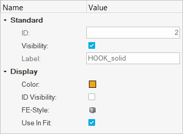
Figure 1.
The Entity Editor is turned on and displayed in the browser
by default; however, you can hide the editor by clicking on the show/hide toggle ![]() (located in the top right
corner). In addition, the Entity Editor can be resized vertically
and horizontally by clicking on the line that separates the editor from the browser or
modeling window (note the double arrow) and dragging and releasing
the mouse button once the desired height or width is reached.
(located in the top right
corner). In addition, the Entity Editor can be resized vertically
and horizontally by clicking on the line that separates the editor from the browser or
modeling window (note the double arrow) and dragging and releasing
the mouse button once the desired height or width is reached.
Components/Parts
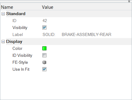
Figure 2.
Standard
- ID
- The ID of the component/part.Restriction: This field is not editable.
- Visibility
- Activate/deactivate the check box to turn the display of the component/part on/off in the modeling window.
- Label
- The label of the component/part.Restriction: This field is not editable.
Display
- Color
- Click the Color box, select a color theme from the drop-down
menu (Default, Median, or Rainbow), pick a color from the palette to change the
component/part color.Tip: Click
 in the
color palette to assign and save custom colors.
in the
color palette to assign and save custom colors. - ID Visibility
- Activate/deactivate the display of the component/part ID using the check box.
- FE Style
- Select/change the element visualization mode of the component/part. The following
options are available:
- Wireframe Elements

- Transparent Elements

- Shaded Elements and Mesh Lines

- Shaded Elements and Feature Lines

- Shaded Elements

- Wireframe Elements
- Use in fit
- Activate the check box to scale the graphic to fit the window with respect to the selected entities in the animation.
Measures
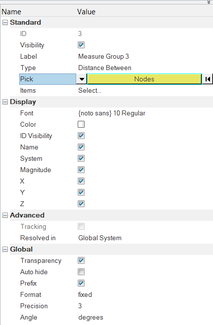
Figure 3.
Standard
- ID
- The ID of the measure group.Restriction: This field is not editable.
- Visibility
- Activate/deactivate the check box to turn the display of the measure group on/off in the modeling window.
- Label
- Click in the field to change the label of the measure group.
- Type
- Select a measure type using the drop-down menu:
- Distance Between
- Incremental Distance
- Minimum Distance
- Position
- Relative Displacement
- Relative Angle
- Angle Between
- Incremental Angle
- Circle Radius
- Yaw Pitch Roll
- Elemental Contour
- Pick
- Select/change the type of entity that will be added to a measure group using the input
collector. You can also left click the collector to display the Select by ID
dialog.Note: For Minimum Distance measure groups, clicking in the field will display the Minimum Distance dialog. Use the input collectors to select From and To entities.
- Items
- Display the Measure Items dialog. Click Delete to remove the
selected items from the Measure Items list, or click Create
Curves to display the Create Curves dialog. This dialog will remain active
until it is closed.Note: For Minimum Distance measure groups only, the Review mode button
 and the Edit button
  will also be displayed in the Measure Items
dialog.
will also be displayed in the Measure Items
dialog.
Display
- Font
- Display the Font Selector dialog which allows you to select the font type, font style, and font size.
- Color
- Select a measure color.
- ID Visibility
- Display the measure group ID.
- Name
- Display the measure group.
- System
- Display the system ID.
- Magnitude
- Display the magnitude value for the selected measure group.
- X
- Display the X value for the selected measure group.
- Y
- Display the Y value for the selected measure group.
- Z
- Display the Z value for the selected measure group.
- True angle
- Display the projected true angle onto the plane.Restriction: Applicable only for angle type measures (Relative Angle, Angle Between, and Incremental Angle).
- x-proj
- Display the projected true angle onto the plane, with the x-axis as the normal.Restriction: Applicable only for angle type measures (Relative Angle, Angle Between, and Incremental Angle).
- y-proj
- Display the projected true angle onto the plane, with the y-axis as the normal.Restriction: Applicable only for angle type measures (Relative Angle, Angle Between, and Incremental Angle).
- z-proj
- Display the projected true angle onto the plane, with the z-axis as the normal.Restriction: Applicable only for a angle type measures (Relative Angle, Angle Between, and Incremental Angle).
- Radius
- Display the radius of the circle for the selected measure group.Restriction: Applicable only for a Circle Radius measure.
- Ctr X
- Display the X-coordinate of the center of the circle for the selected measure
group.Restriction: Applicable only for a Circle Radius measure.
- Ctr Y
- Display the Y-coordinate of the center of the circle for the selected measure
group.Restriction: Applicable only for a Circle Radius measure.
- Ctr Z
- Display the Z-coordinate of the center of the circle for the selected measure
group.Restriction: Applicable only for a Circle Radius measure.
Advanced
- Tracking
- Change the resolved in system to a tracking system.
- Resolved in
- Select a system using the input collector. You can also hold down Shift and left click the collector to display the Select by ID dialog.
Global
- Transparency
- Activate/deactivate the transparency mode.
- Auto hide
- Hide the measure group box when the selected entities are not visible on the screen.
- Format
- Select the Fixed or Scientific format from the drop-down menu.
- Precision
- Increase or decrease the precision level using the up/down arrows.
- Angle
- Select Degrees or Radians for the angle using the drop-down menu.
Notes
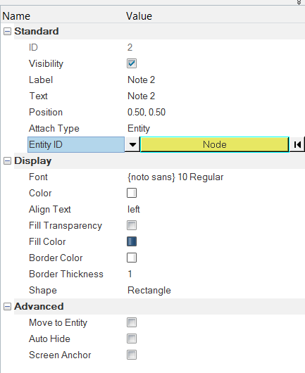
Figure 4.
Standard
- ID
- The ID of the note.Restriction: This field is not editable.
- Visibility
- Activate/deactivate the check box to turn the display of the note on/off in the modeling window.
- Label
- Click in the field to change the label of the note.
- Text
- Display the Note Text dialog. You can update the note text in the Description box by entering text directly, or by selecting a field name clicking Insert Field. You can also enter a Templex expression directly into the Description box.
- Position
- Allows you to change the position of the note.
- Attach Type
- Select the anchoring method for note using the drop-down menu:
- Window (*Default)
- Entity
- Coordinates
Display
- Font
- Display the Font Selector dialog which allows you to select the font type, font style, and font size.
- Color
- Select a note color.
- Align Text
- Select the text alignment (within the note box) from the drop-down menu:
- Left
- Center
- Right
- Fill Color
- Select a fill color for the note box. You must remove the check mark from the Fill Transparency option in order to select a fill color.
- Fill Transparency
- Remove the color from the note box and make it transparent against the window.
- Border Color
- Select a border color.
- Border Thickness
- Select the border line thickness for the note box from the drop-down menu:
- 0 (no border)
- 1
- 2
- 3
- 4
- Shape
- Select the outline shape of the note:
- Rectangle
- Circle
- Ellipse
Note: This is option is only available only in the Entity Editor (it is not available in the Notes panel).
Advanced
- Move to Entity
- Position the note at the attachment location.Note: This option is disabled if Window has been selected from the Attach To drop-down menu.Activating the Move to entity check box will automatically override the Anchor to Screen option (if activated).
- Auto Hide
- Hide the note box when the entity that the note is attached to is not visible on the screen.
- Screen Anchor
- Keep the note stationary during animation or when manipulating the model view
(rotating, zooming, etc.).Note: This option is disabled if Window has been selected from the Attach To drop-down menu.
Properties
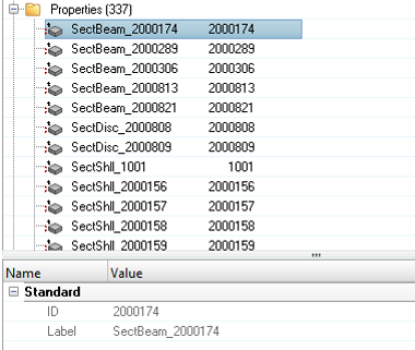
Figure 5.
Standard
Current Entity Editor support for Properties is limited to viewing only.- ID
- The ID of the property.Restriction: This field is not editable.
- Label
- The label of the property.Restriction: This field is not editable.
Section Cuts
Whenever a section cut is selected in the Results Browser, the manipulator will be active and ready to be edited.
Section Cuts - Planar
Standard
- ID
- The ID of the section cut.Restriction: This field is not editable.
- Type
- The section cut type (Planar).Restriction: This field is not editable.
- Visibility
- Activate/deactivate the check box to turn the display of the section cut on/off in the modeling window.
- Label
- Click in the field to change the label of the section cut.
- Orientation
- Click to display the Section Plane dialog, which allows you to change/define the plane of the section cut.
- Base
- Specifies the x, y, and z coordinates of the base point of the section cut plane.
- Normal
- Specifies the direction cosines of the normal of the section cut plane.
Display
- Cross Section Only
- Display a cross section of the section cut.
- Clip Above
- When activated, the portion of the model along the positive side of the section plane’s normal will be clipped.
- Deformable
- Allow the section cut to be deformed, along with the components, during animation.
When this option is selected, a time step/frame number is added next to the section cut label in the Results Browser and in the Section Cut panel.
- Cross Section Width
- Adjust the width of the cross section using the slider bar. The Cross Section Only check box (see above) must be activated in order for the slider bar to be displayed.
- Clip Elements
- Display the elements of the clipped part of the model.
- Show Section Color
- Change the section cut color.
- Section Color
- Select a color from the palette. The Show Section Color check box (see above) must be activated in order for the selected color to be displayed.
- Grid
- Display the grid lines in the modeling window.
- Grid Text
- Display the grid line text in the modeling window.
- Grid Text Precision
- Select the precision to be used for the grid line text value using the combo box.
- Grid Line Space X
- Change the spacing of the grid lines along the section plane's x direction
- Grid Line Space Y
- Change the spacing of the grid lines along the section plane's y direction
Global
- Feature Lines
- Display the feature lines of the clipped part of the model.
- Transparency
- Display the clipped part of the model as a transparent surface.
Section Cuts - Spherical
Standard
- ID
- The ID of the section cut.Restriction: This field is not editable.
- Type
- The section cut type (Spherical).Restriction: This field is not editable.
- Visibility
- Activate/deactivate the check box to turn the display of the section cut on/off in the modeling window.
- Label
- Click in the field to change the label of the section cut.
- Center Node
- Click to display the Node collector, which allows you to adjust the position of the base point of the section cut to the center node.
- Center
- Specifies the x, y, and z coordinates of the base point of the section cut. Click in the field to manually enter in coordinates if desired.
- Radius
- Specifies the radius of the spherical section cut. Click in the field to manually adjust the radius of the sphere
Display
- Cross Section Only
- Display a cross section of the section cut.
- Clip Inside
- Displays the cross section of the section cut inside the sphere when unchecked.
- Sphere
- Displays a sphere.
- Deformable
- Allow the section cut to be deformed, along with the components, during animation.
When this option is selected, a time step/frame number is added next to the section cut label in the Results Browser.
- Show Section Color
- Change the section cut color.
- Section Color
- Select a color from the palette. The Show Section Color check box (see above) must be activated in order for the selected color to be displayed.
- Clip elements
- Display the elements of the clipped part of the model.
Global
- Feature Lines
- Display the feature lines of the clipped part of the model.
- Transparency
- Display the clipped part of the model as a transparent surface.
Sets
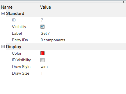
Figure 6.
Standard
- ID
- The ID of the set.Restriction: This field is not editable.
- Visibility
- Activate/deactivate the check box to turn the display of the set on/off in the modeling window.
- Label
- Click in the field to change the label of the set.
- Entity IDs
- Lists the number of entities in the active set. Click in the field to activate the input collector, which allows you to select/change the entity type of a set. You can also hold down Shift and left click the collector to display the Extended Entity Selection dialog.
Display
- Color
- Select/change the color of the feature lines of the entities in a set using the color box and palette.
- ID Visibility
- Display the IDs of entities in a set/group.
- Draw Style
- Select the drawing style for the active set using the input collector:
- shaded (for Component sets only)
- wire (for Component or Element sets only)
- point (for Node sets only)
- sphere (for Node sets only)
- Draw Size
- Change the thickness of the wire and the size of the point/sphere drawing for the active set.
Views
Views - Orthographic
Standard
- Label
- The ID of the view.Restriction: This field is not editable for Current View.
- Lock
- Activate to lock the view.
- With Masking
- Activate to save the current mask state to the view.
View Projection
- Projection Type
- Select/change the projection type of the view (Orthographic, Perspective, or Lens).
Views - Perspective
Standard
- Label
- The ID of the view.Restriction: This field is not editable for Current View.
- Lock
- Activate to lock the view.
- With Masking
- Activate to save the current mask state to the view.
View Projection
- Projection Type
- Select/change the projection type of the view (Orthographic, Perspective, or Lens).
- Perspective Angle
- Click in the field and use the slider bar to adjust and set the angle of the perspective (from 5 to 45 degrees).
Views - Lens
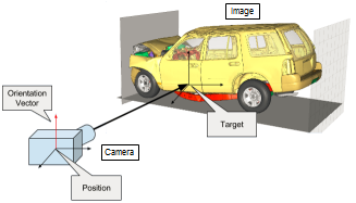 Figure 7. Camera and Model Example |
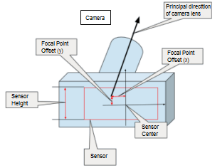 Figure 8. Camera Example |
Standard
- Label
- The ID of the view.Restriction: This field is not editable for Current View.
- Lock
- Activate to lock the view.
- With Masking
- Activate to save the current mask state to the view.
Camera
- Target
- The coordinates of the point on the 3D model where the camera is focused on. There is no default value, a user defined value should always be provided.
- Position
- The coordinates of where the camera is in 3D model space. There is no default value, a user defined value should always be provided.
- Orientation Method
- Define which direction the top of the camera is pointing towards:
- X-up
- X-down
- Y-up
- Y-down
- Z-up
- Z-down
- Vector (Default)
- Orientation Vector
- When an orientation method is chosen as any predefined method (XYZ axis and up or down), the orientation vector is automatically assigned with corresponding vectors. The default value is 0.33, 0.33, 0.33. When the orientation method is set to Vector, you can arbitrarily input a vector. This vector is an approximation of which direction the top of camera is pointing towards.
- Up Vector
- The actual direction the top of the camera is pointing towards. This value is calculated automatically based on the previous four entries. It is normalized, and is not editable.
View Projection
- Projection Type
- Select/change the projection type of the view (Orthographic, Perspective, or Lens).
- Focal Length (Zoom)
- The focal length of the camera lens in millimeters. This typically can be read from the camera lens. The default value is 25.0.
- Sensor Height (mm)
- The height of the camera sensor in millimeters. This typically can be found in the camera specifications. Some camera manufacturers specify a sensor width or diagonal, if that is the case the height needs to be calculated using the aspect ratio of the image/video. The default value is 15.6.
- Focal Point Offset (mm)
- Focal point is the intersection point between the principal direction of camera lens and the camera sensor plane. The Focal Point Offset is the difference from this point to center of camera sensor in millimeters. The default value is (0.0, 0.0). If the actual value is not known, the default value can be used.
Image Plane
- Image Plane ID
- The ID of the image plane for which cropping information is input.
- Top cropping
- Pixels cropped at the top.
- Bottom cropping
- Pixels cropped at the bottom.
- Left cropping
- Pixels cropped at the left.
- Right cropping
- Pixels cropped at the right.
- Adjusted sensor height (mm)
- This is calculated by HyperView as follows:
Adjusted sensor height =
video height * sensor height/(top + bottom + video
                  height)
where;
top: pixels cropped at the topbottom: pixels cropped at the bottomvideo height: vertical resolution in pixelsRestriction: This field is not editable. - Adjusted focal point
- This is calculated by HyperView as follows:
The x value of new focal point offset =
(left - right) / 2.0 / video height +
                  input focal point offset x
The y value of new focal point offset =
(bottom - top) / 2.0 / video height + input focal point offset
                y
Restriction: This field is not editable.
Model Files
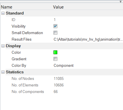
Figure 9.
Standard
- ID
- The ID of the model file.Restriction: This field is not editable.
- Visibility
- Activate/deactivate the check box to turn the display of the note on/off in the modeling window.
- Small deformation
- Activate to change the elemental system definition for transient results. The elemental system will be defined using model simulation step coordinates instead of current simulation step coordinates.
- Result files
- Click in the value field to bring up the Result File List dialog that displays the list of result files associated with the model.
Display
- Color
- Select/change the color of the model using the color box and palette.
- Gradient
- Activate/deactivate to turn the model gradient on/off.
- Color By
- Select the color by mode for the selected model using the drop-down menu:
- component
- model
- normal
- part
Statistics
- No of Nodes
- The number of nodes contained in the selected model.
- No of Elements
- The number of elements contained in the selected model.
- No of Components
- The number of components contained in the selected model.
Parts View - Components
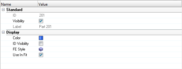
Figure 10.
Standard
- ID
- The ID of the part assembly.Restriction: This field is not editable.
- Visibility
- Activate/deactivate the check box to turn the display of the part assembly on/off in the modeling window.
- Label
- Click in the field to change the label of the part assembly.
Display
- Color
- Click the Color box to select a part assembly color from the pop-up dialog.
- ID Visibility
- Activate/deactivate the display of the part assembly ID using the check box.
- FE Style
- Select/change the element visualization mode of the part assembly. The following
options are available:
- Wireframe Elements
- Transparent Elements
- Shaded Elements and Mesh Lines
- Shaded Elements and Feature Lines
- Shaded Elements
- Wireframe Elements
- Use In Fit
- Activate the check box to scale the graphic to fit the window with respect to the selected entities in the animation.
Parts View - Parts/Part Assemblies
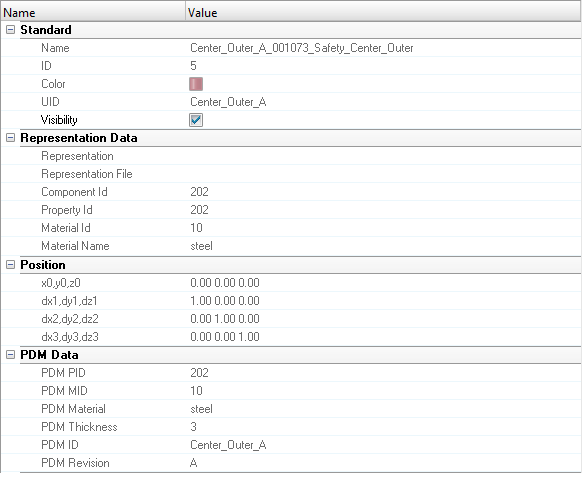
Figure 11.
Certain representation data and PDM data attributes displayed in the Entity Editor correspond to the columns displayed in the pane above the Entity Editor in the Results Browser. This information is read only.
Standard
Displays attributes that are unique to the part or assembly.Parts and part assemblies require a unique name and a unique identifier (UID), both of which can contain alphanumeric characters. The UID is an optional field that is utilized in part representation management and import model entity management. For example, when merging a component with a part (module), the two entities will be matched using the UID if it exists. If a UID does not exist, merging will be based on the part name.
- Name
- The name of the component/part.
- ID
- The ID of the component/part.
- Color
- Click the Color box to select a component/part color from the pop-up dialog.
- UID
- The unique ID of the component/part.
- Visibility
- Activate/deactivate the check box to turn the display of the component/part on/off in the modeling window.
Representation Data
Displays attributes that are specific to a part representation.- Representation
- The name of the representation
- Representation File
- The location of the representation file.
- Component ID
- The component ID.
- Property ID
- The property ID.
- Material ID
- The material ID.
- Material Name
- The name of the material.
Position
Displays the 4 x 3 transformation matrix of a part, namely its translation, rotation, and scaling.- x0,y0,z0
- dx1,dy1,dz1
- dx2,dy2,dz2
- dx3,dy3,dz3
PDM Data
Displays PDM attributes.- PDM PID
- PDM PID
- PDM MID
- PDM MID
- PDM Material
- PDM Material
- PDM Thickness
- PDM Thickness
- PDM ID
- PDM ID
- PDM Revision
- PDM Revision
Image Planes
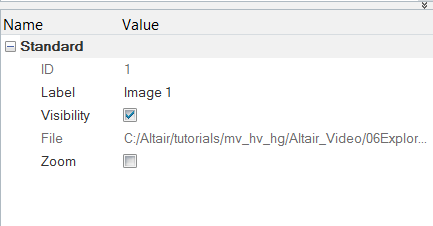
Figure 12.
Standard
- ID
- The ID of the image plane.Restriction: This field is not editable.
- Label
- The label of the image plane.
- Visibility
- Turn the display of the image plane on/off in the modeling window.
- File
- The path of the image plane file.Restriction: This field is not editable.
- Zoom
- Activate to zoom the image plane along with the model.