Driveline
The driveline transmits the power from the power source to the driving wheel.
The power is transmitted by either a Chain or a Belt that connects the gear box output shaft and the rear wheel. In the library, this mechanism is modeled using a combination of Forces, Joints, Markers and SolverVariables.
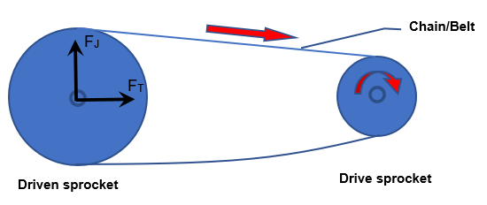
Figure 1.
The Drive sprocket is drawing the power from the gear box output shaft. This power (or the resulting motion) is in turn driving the Driven sprocket which is fixed to the rear wheel. The red sold arrows indicate the rotational motion of the sprocket and the linear motion of the chain.
- FT: Tension or pulling force.
- FJ: Jacking or vertical force due to the chain being pulled on the tighter side by the Drive sprocket.
If the sprockets are not in the same plane, a lateral force also acts between them. In the Two-Wheeler library, this force is not modeled.
Modeling the Driveline Forces
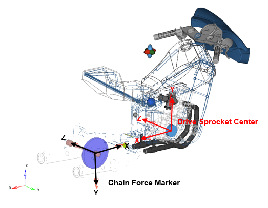
Figure 2.
- Vector
- Driven Sprocket Spin Axis: A vector that defines the rear wheel spin/Driven sprocket spin axis.
- Bodies
- Chain solution dummy: A dummy body that is constrained such that it remains at the rear wheel center and orients such that the line of sight is maintained between Drive and Driven sprockets.
- Markers
- Two Markers are needed:
- Chain Force Marker: Marker on Chain solution dummy @ Driven/Rear
sprocket center with
- X axis pointing towards the front sprocket center
- Z axis pointing along the rear wheel/sprocket spin axis
- Drive Sprocket Center: Marker on Engine/Drive sprocket @
Drive/Front sprocket center with
- X axis pointing towards the rear sprocket center
- Z axis pointing along the gear box output shaft spin axis
- Chain Force Marker: Marker on Chain solution dummy @ Driven/Rear
sprocket center with
- Joints
- The following Joints model the chain alignment:
- Chain dummy to driven sprocket: Ball joint between Chain solution dummy and rear wheel
- Drive sprocket to chain dummy: Inline joint between Engine/Driver sprocket and Chain solution dummy – pointing towards Driven/Rear sprocket center
- Chain Plane Y to Driven Sprocket: Inplane joint between Chain solution dummy and rear wheel – with the Normal along the Driven sprocket spin axis
These three joints constrain the Chain Force Marker (on Chain solution dummy) such that:- The X axis is pointing towards the Drive sprocket center
- The Z axis is pointing along the rear wheel spin axis
- Force
- The chain force element is created using the Chain Force Marker as
reference. The force acts between Rear Wheel and Engine/Drive sprocket.
The component forces are:
- Fx: acting along the line joining the sprockets - Chain tension resulting from the engine torque (FT)
- Fy: acting along the Normal to Fx– Jacking force resulting from the engine torque (FJ)
- Tz: acting about the spin direction – Engine torque scaled by the ratio of the sprocket sizes.