The Road Graphics Builder creates a graphic representation of a road description file which
you can use to visualize the road surface in MotionSolve and
HyperView.
The Road Graphics Builder supports the following commonly used road description files:
Curved Regular Grid (CRG)
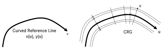
A Curved Regular Grid (CRG) road is comprised of node data on a centerline/curved reference
line (u-axis) along with node data along lines orthogonal to the centerline (v-axis). The
u-axis has nodes ‘ubeg’ and ‘uend’ denoting the beginning and ending nodes of the
centerline. The orthogonal lines to the centerline/reference line have values ranging from
‘vmin’ to ‘vmax’. (x,y) coordinates are obtained by querying the (u,v) coordinates. (z)
coordinate is obtained by querying the (x,y) coordinates from the previous step. Figure 1.
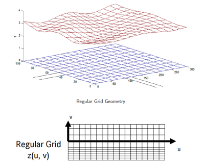
Regular Grid Road (RGR)
A Regular Grid Road has data points that are equally spaced in the x- and y- directions.
The grid data are defined by:
xmin, ymin: the grids minimum value in x- and y- directions
respectively.
∆x, ∆y: the grids constant mesh size in x- and y- directions respectively.
nx, ny: the number of grid nodes in x- and y- directions
respectively.
Figure 2.
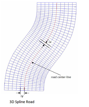
3D Spline Road
Regular grid data files can be combined with curvilinear road centerlines to form TeimOrbit
data files of type ‘3D Spline’. The road centerline, as defined in the RDF-file, is used as
curvilinear x-axis of the grid. X data points are equidistant along the centerline with a
spacing of ∆x. The x-coordinate starts with value 0 at the beginning of the road, which is
defined by the first data point in the RDF-file. The grid’s y-coordinate is chosen
perpendicular to the centerline, in other words it coordinates with the centerline’s normal
in the road surface. Positive y- values define grid points that are located on the left of
the centerline, if viewed along the direction of increasing x-values. Figure 3.