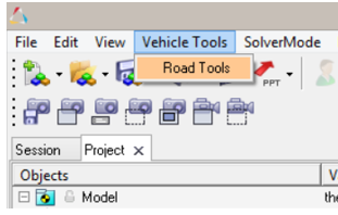
Select Road Graphic Tools from the MotionSolve Vehicle
Tools menu. Figure 1.
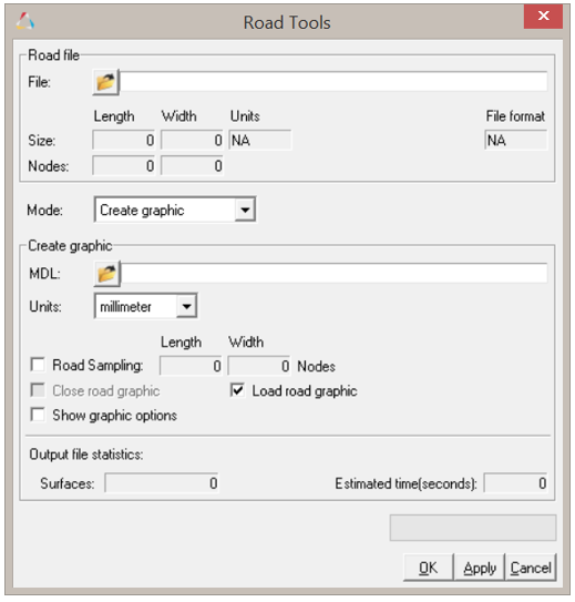
Upon selecting, the following dialog is displayed: Figure 2.
The steps to create a road graphic are outlined below.
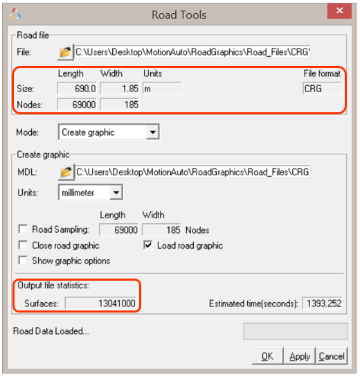
Selecting the input road file:
On populating the input road file path, the road file is parsed to detect the
road file type and populate the length and width of the road. The input road
file has data point written either in ASCII or binary format. The parser reads
the sampling of file along length and the width of the road to determine the
original data sampling in the input road file. Figure 3.
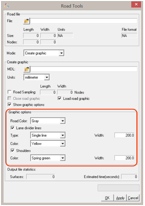
Graphic options:
The Graphic Options are preset to show a centerline and shoulder graphic.
Activating the Show graphic options check box will expand
the dialog, allowing you to append the graphic options and their parameters. Figure 4.
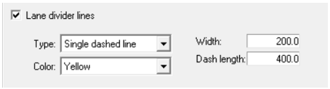
Lane Divider Graphic:
This option is used to activate centerline in the output graphic. The
tools provide four options for centerline:
Single Line
Single Dashed Line
Double Line
Double Dashed Line
When a lane divider line is selected the width of centerline has
to be selected. The units of the width are same as the output
graphic units. Upon selection of dashed centerline (single or
double), an additional option for dash length is activated and the
units of dash length are again in graphic units. By default, a
preset centerline width and dash length is given. Figure 5.
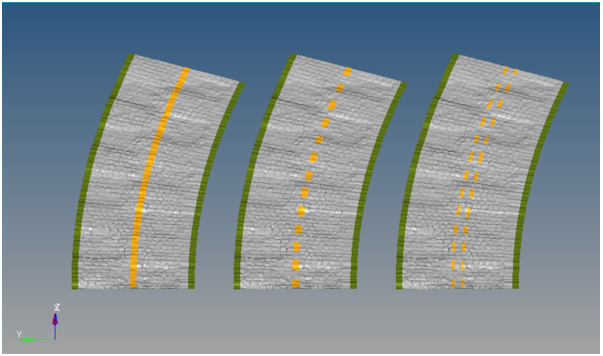
A graphic representation of a road with different lane
divider lines is shown below: Figure 6. Single Line (left), Single Dashed Line (mid), Double
Dashed Line (right)
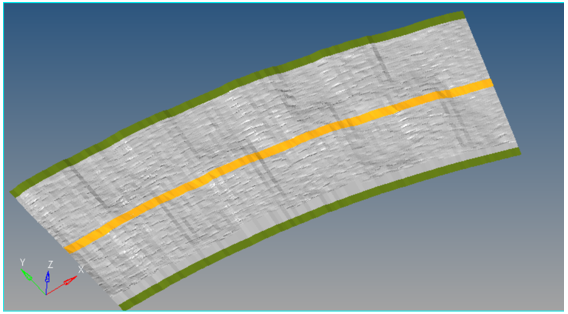
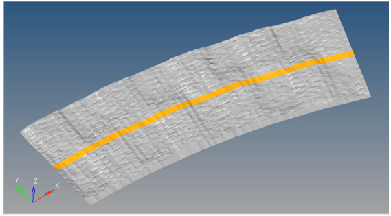
Shoulder Graphics:
This option generates a shoulder on both sides of the road. When the
Shoulders option is selected, the width field of shoulder is activated
and you can edit this field to set the shoulder width. A graphic entity
comparison of a road with and without shoulders is shown below: Figure 7. Road with shoulders Figure 8. Road without shoulders
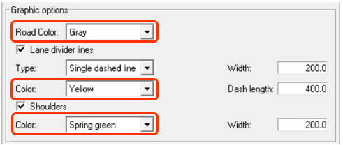
Color of Road Graphic Components:
The components of road graphic (road, centerline, shoulders) can be
assigned different colors by selecting them from the drop-down menu.
Figure 9.
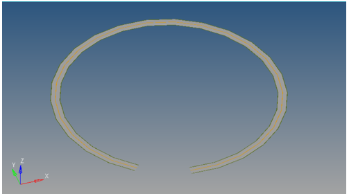
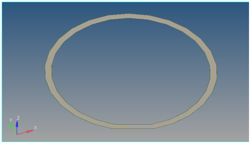
Close Graphic:
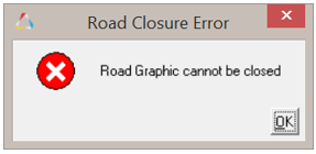
Select this option to close the road graphic to form a circuit. When you
select this option the Road Graphics Builder evaluates whether the road can be
closed. If not, the Road Graphics Builder displays this alert and the Close road
graphic check box will be deactivated. Figure 10. Graphic entity with the "Close road graphic" option not
selected Figure 11. Graphic entity with the "Close road graphic" option selected Figure 12. Road Graphic Closure Error message
The road closure criterion is based on following two metrics:
The distance between start and end points is less than 1% of total
road length.
The angle between the starting and ending tangents is less than 40
degrees.
Graphic Units:
By default the graphic units are selected as “millimeter” with respect any
input road file units. This option gives you the flexibility to select the
output graphic file unit: millimeter,
centimeter, meter,
kilometer, feet, inch, or
mile. The output graphic is thus scaled likewise. All of
the parameters in graphic options are according to graphic output units.
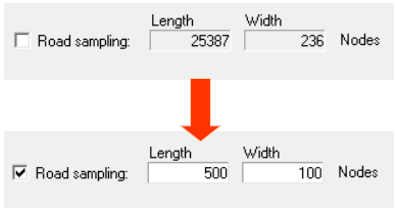
Output File Graphic Sampling:
You can also control the resolution of output file graphic by changing the
"Total nodes along length” and “Total nodes along width” parameters, in order to
make a coarse or a fine graphic. By default, the Road Sampling check box is
enabled to generate the output graphic using the same sampling as the input road
file. Figure 13.
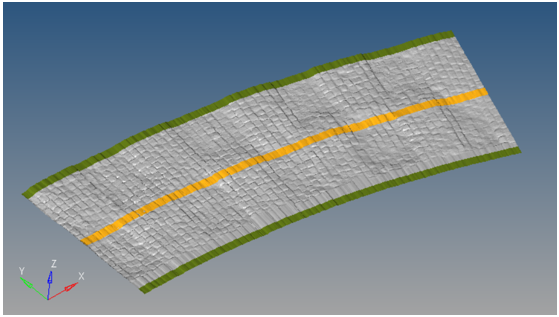
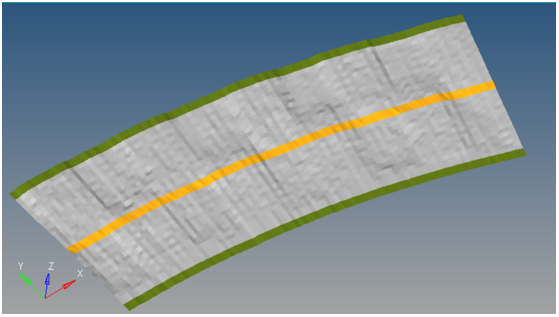
A high number of nodes will result in more of the surface being created
in the graphic and would be computationally expensive. For larger files, it
is recommended to lower the number of nodes for faster creation of a
graphic. Figure 14. Fine mesh/high sampling example Figure 15. Coarse mesh/low sampling example
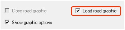
Load Road Graphic:
By default the Road Graphic that is generated is loaded to the model file. The
Load road graphic options provide you with an option not to load the Road
Graphic onto the model after the creation of the .obj
file. Figure 16.
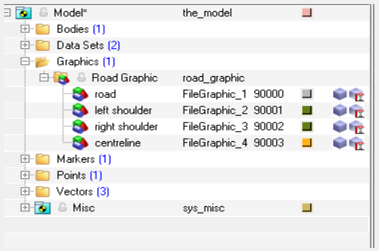
Road Graphic Output:
Builder is designed as a one click interface to create and load graphic in the
current MotionView window. The Graphic Output is
loaded as a Graphic System with FileGraphic as its components (road, left
shoulder, right shoulder, centerline). Figure 17.
Depending on the graphic options selected, the components may vary from
1 (for single road component) to 5 (road with double centerline and
shoulders).
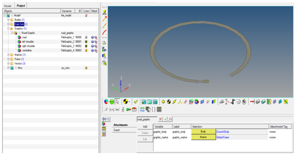
The output graphic is saved as a Graphic System of file
graphic in a MotionView model file. By default,
the output graphic model is saved in same working directory as the input
road description file and has the same file name with an
.mdl extension. You do however have the option to
change this destination by changing file path in the output graphic path.
Figure 18.
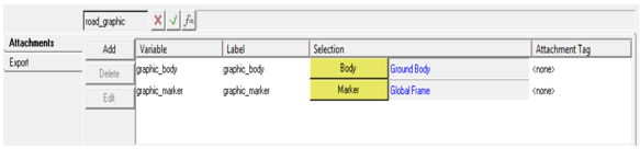
The Output graphic has two attachments, “graphic body” and
“graphic marker”, in order to seamlessly integrate the road graphic into
existing models. By default, the graphic body is resolved to the Ground Body
and the graphic marker is resolved to the road marker (if it exists), or
else to the Global Marker. Figure 19.
Reusability of a Road Graphic:
The saved output graphic can be imported into any of the models using the
import option. Also along with the saved model file, the graphic builder saves
the .obj in the same destination directory. Both of these
files can be reused.