Tire Contact Methods
- Single Point Contact
- Elliptical Cam Contact Model
The Single Point Contact method is used if ‘CONTACT_MODEL’ key is not present in the [MODEL] block in the tire property file. To choose the Cam Contact method please use the following key value in [MODEL] block:
CONTACT_MODEL = ‘3D_ENVELOPING’
Single Point Contact
This is the default contact method that is used with the Fiala model. This model assumes the "disc" shape for the tire and rim and calculates the contact point at the intersection of the wheel plane with the road tangent.Motorbike tires have more curvature when compared with a car tire. At an inclination angle, the theoretical contact point shifts in the lateral direction. The geometry of the tire carcass is used to model this behavior.
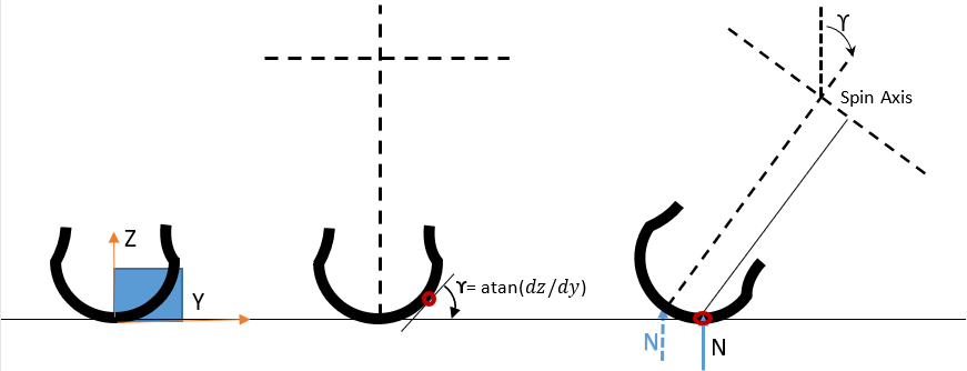
Figure 1. From left: Tire cross section data needed for contact point evaluation | Tire at 0 camber angle | Tire at ϒ camber angle
The SECTION_PROFILE_TABLE contains the data of the tire carcass. The table should contain two columns as shown below:
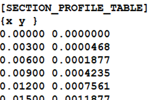
The {x y} in the above table serves as the label. The table is read as per the TYDEX-W coordinate system and it represents the height variation of carcass with respect to points along the carcass width. Data for only a quarter of tire carcass is needed as the tire is assumed symmetric about XY plane in ISO system. The data points should be monotonically increasing otherwise data points will be ignored and the tire contact with will be calculated assuming a rectangular tire carcass.
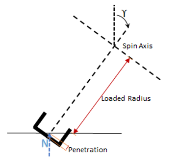
Figure 2. Single Point Contact Method Without Carcass Shape
Contact Patch Dimensions: PA1 and PA2 show the variation of the contact patch length. The size of the contact patch increases with increasing vertical load. The dimension of the contact patch can be obtained by pressing the tire on carbon paper or by using ink.
| Parameter | Details | Unit |
|---|---|---|
| PA1 | Coefficient of the square root term in the contact length equation. | - |
| PA2 | Coefficient of the linear term in the contact length equation. | - |
If the above parameters are found in the “PARAMETER” block of tire property file, then the contact patch length is evaluated as follows:
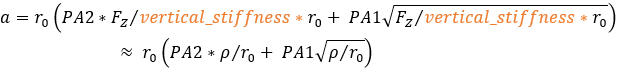
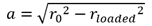
Where  is the tire penetration and
  is the unloaded radius of the tire.
In case the PA1 and PA2 parameters are not found, then the tire is assumed to be a rigid disc of a radius equal to the unloaded radius and the contact patch length is evaluated as follows:
Contact Width Equation:

Where a, b are effective half-length and half-width of the contact patch.
 is the width of the tire.
Elliptical Cam Contact Model
- Effective road height variation

- Effective slope variation

- Effective curvature

- Camber change

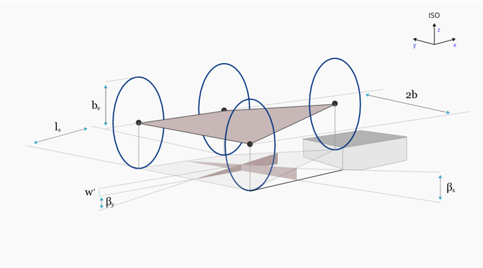
Figure 3. 3D Elliptical Cam Contact Arrangement
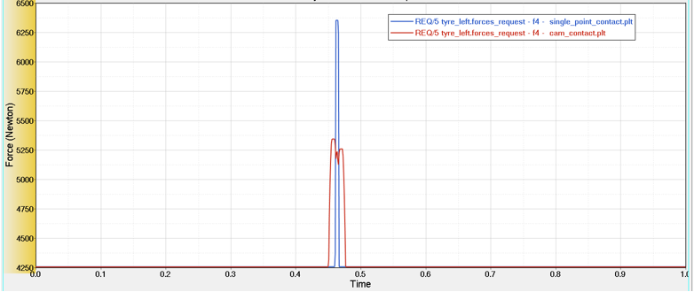
Figure 4. Vertical force at constant axle height when tire is rolled over a cleat (10 mm height, 50 mm length) at constant velocity of 10.833 m/sec (39km/h)
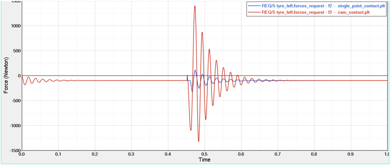
Figure 5. Longitudinal force at constant axle height when tire is rolled over a cleat (10 mm height, 50 mm length) at constant velocity of 10.833 m/sec (39km/h)
The results show that single point contact model predicts higher values of vertical force because it traces the obstacle, however the actual force experienced by the tire is less which is closely predicated using cam contact method.
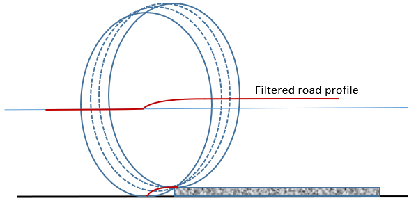
Figure 6. Filtered Road Profile Using a Series of Cams
How to Use a Cam Contact Model
To use a cam contact method with Fiala Tire, the following attribute should exist in the [MODEL] block:
CONTACT_MODEL = '3D_ENVELOPING'
| Parameters | Details | Unit |
|---|---|---|
| PA1 | Coefficient of the square root term in the contact length equation. | - |
| PA2 | Coefficient of the linear term in the contact length equation. | - |
| PAE | Half of the ellipsoid length. | Length |
| PBE | Half of the ellipsoid height. | Length |
| PCE | Order of the ellipsoid. | - |
| PLS | Scaling of the distance between the front and rear ellipsoid. | - |
| ROAD_INCREMENT | Mesh size for the ellipsoid. | Length |
| N_WIDTH | Number of cams along the contact width. | - |
| N_LENGTH | Number of cams along the contact length. | - |
| MESH_HEIGHT | Height of the end points of the ellipse mesh. It should be greater than the obstacle height. |
PA1 and PA2 show the variation of the contact patch length. The size of the contact patch increases with increasing vertical load. The dimension of the contact patch can be obtained by pressing tire on carbon paper or by using ink.
Contact Length Equation:
Where is the tire penetration and is the unloaded radius of the tire.
Contact Width Equation:
Where a, b are effective half-length and half-width of the contact patch.
is the width of the tire.
The equation for the shape of cam can be written as:
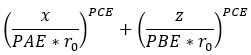
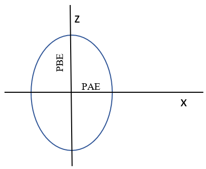
Figure 7. Cam Dimension
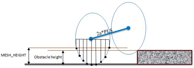
Figure 8. Cam with Two Point Follower
In case no data is available, a good estimate of PAE and PBE is equal to tire radius. The ellipse dimension can be calculated by measuring the outside contour of tire when it touches the obstacle. For PLS a 0.8 is a good value to use. ROAD_INCREMENT decides the meshing size of road it directly affects the computation time of model.