Engine Speed Controller
The Engine speed based shift controller upshifts whenever engine speed goes above the
upshift RPM, and it downshifts when the engine speed goes below the downshift RPM. The Gear
shift controller also controls the throttle and clutch signal as shown in the figure
below.
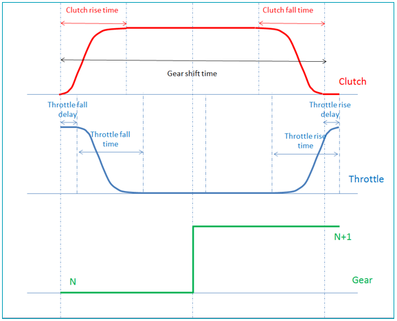
Figure 1. Gear shift time diagram
Figure 1. Gear shift time diagram
The Gear clutch controller also, cuts the throttle signal as shown in the time diagram of a
gear
shift.
[GEAR_CLUTCH_CONTROL]
TAG = 'ENGINE_SPEED'
 (GEAR_SHIFT_MAP)
| {G | US | DS | CT | CRT | TFD | TFT | CFT | TRD |
|---|---|---|---|---|---|---|---|---|
| 1 | 650 | 125 | 0.45 | 0.05 | 0.1 | 0.1 | 0.05 | 0.05 |
| 2 | 650 | 125 | 0.45 | 0.05 | 0.1 | 0.1 | 0.05 | 0.05 |
| 3 | 650 | 125 | 0.45 | 0.05 | 0.1 | 0.1 | 0.05 | 0.05 |
| 4 | 650 | 125 | 0.45 | 0.05 | 0.1 | 0.1 | 0.05 | 0.05 |
| 5 | 650 | 125 | 0.45 | 0.05 | 0.1 | 0.1 | 0.05 | 0.05 |
| [GEAR CLUTCH CONTROLLER] | ||
|---|---|---|
| TAG | Attr - string | REQUIRED <ENGINE_SPEED> |
| G | Attr – int | REQUIRED
|
| US | Attr – real | REQUIRED
|
| DS | Attr – real | REQUIRED
|
| CT | Attr – real | REQUIRED
|
| CRT | Attr – real | REQUIRED
|
| TFD | Attr – real | REQUIRED
|
| TFT | Attr – real | REQUIRED
|
| CFT | Attr – real | REQUIRED
|
| TRD | Attr – real | REQUIRED
|
| TRT | Attr – real | REQUIRED
|
| {G | US | DS | CT | CRT | TFD | TFT | CFT | TRD |
|---|---|---|---|---|---|---|---|---|
| 1 | 650 | 125 | 0.45 | 0.05 | 0.1 | 0.1 | 0.05 | 0.05 |
| 2 | 650 | 125 | 0.45 | 0.05 | 0.1 | 0.1 | 0.05 | 0.05 |
| 3 | 650 | 125 | 0.45 | 0.05 | 0.1 | 0.1 | 0.05 | 0.05 |
| 4 | 650 | 125 | 0.45 | 0.05 | 0.1 | 0.1 | 0.05 | 0.05 |
| 5 | 650 | 125 | 0.45 | 0.05 | 0.1 | 0.1 | 0.05 | 0.05 |