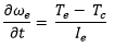
Theory and Equations
The engine and the clutch are modeled as mathematical equations in the IC Engine Powertrain. The state of the Engine is determined by engine speed and the Clutch by the Clutch slip. Following is a list of symbols used to describe the model in this section:
| Engine Speed [State] |  |
| Clutch Slip [State] |  |
| Clutch Torque |  |
| Engine Torque |  |
| Clutch Clamp Force Factor |  |
| Engine Inertia |  |
| Clutch Stiffness |  |
| Clutch Damping |  |
| Transmission RPM | |
| Clutch Capacity |  |
Engine model
The engine is modeled as a black-box that produces a torque based on the current throttle
position (input) and engine speed (state). The rotational inertia of all the rotating
components of the engine are lumped in . The torque to accelerate the engine’s rotating components is the
difference between the torque the engine produces and torque reacted by the clutch. Hence,
the derivative of the engine state (speed) is given by:
The engine torque is:
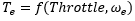
which is interpolated from a 3-D spline that is an input in the .pwr file.
Clutch model
The clutch is modeled as a stiff spring and damper that has the capability of transmitting
torque from the engine to the gear box based on the clutch demand input signal. The output
clutch torque () is an input to the gearbox.
The state of the clutch is defined by the clutch slip (). The clutch torque is determined by the equation:
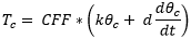
and + to ensure the clutch capacity is not exceeded. CFF is the Clamp
Force Factor, it is determined by running the clutch demand through a step function as shown
in the diagram below (which assumes clutch scaling = 1.0):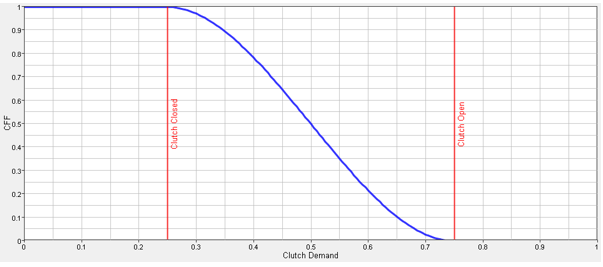
Figure 1.
The clutch demand is the driver’s input on the clutch pedal. Clutch demand is non-dimensional: zero (0) clutch demand represents the driver’s foot off the clutch-pedal, while one (1) clutch demand represents the driver pushing the clutch-pedal to the floor. The derivative of the clutch slip state is determined by the following equation:
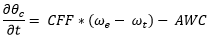
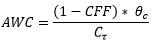
Where the AWC is the anti-windup component described below.
Anti-windup system
When the clutch is disengaged and subsequently re-engaged, some residual clutch slip is
induced into the clutch that keeps the clutch slip at a non-zero value while disengaged.
However, in a real situation the plate is free during the disengaged period and the clutch
slip must return to zero in a finite time ( ) after the disengagement. This has to be modeled into the system.
Hence, the AWC component is included into the derivative of the clutch slip which would
cause the clutch slip to go to zero.
) after the disengagement. This has to be modeled into the system.
Hence, the AWC component is included into the derivative of the clutch slip which would
cause the clutch slip to go to zero.
Anti-Stall system
Rev-limiter
The rev-limiter is an optional system that can be switched on and off in the powertrain depending upon the rev-limiter flag model parameter. This prevents the engine speed from exceeding the engine rev-limit by cutting throttle when the engine speed exceeds the limit.