Electric Power Assisted Steering System
A power assisted steering system that helps driver steer the vehicle by adding controlled energy to the steering system, making it easier for drivers to perform a turn or a maneuver.
- A Hydraulic Power Assisted Steering System (HPAS) which uses a pump providing pressure in a fluid through a hydraulic system connected with cylinders to the rack-pinion assembly, reducing driver’s effort.
- An Electric Power Assisted Steering System (EPAS) which uses a DC electric motor providing a controlled assist torque to the steering system.
Electric Power Assisted Steering Systems have become more popular during the years for several reasons. Firstly, an EPAS system can be easily “tailored” to its individual needs by having different behavior for different vehicle velocities. Most EPAS systems in the market tend to provide higher assist when vehicle is moving at slow speed and reducing it for faster vehicle’s speed. Also, unlike a HPAS that continuously drives a hydraulic pump to maintain system pressure, the efficiency advantage of an EPAS system is that it powers the EPAS motor only when necessary. This results in reduced vehicle fuel consumption compared to the same vehicle with an HPAS. Finally, an EPAS system consists of less parts and needs less maintenance making it more appealing as a power assisted steering system.
There are four forms of EPAS systems based on the position of the assist motor. They are the column assist type (C-EPS), the pinion assist type (P-EPS), the direct drive type (D-EPS) and the rack assist type (R-EPS). The C-EPS type has a power assist unit, torque sensor, and controller all connected to the steering column. In the P-EPS system, the power assist unit is connected to the steering gear's pinion shaft. This type of system works well in small cars. The D-EPS system has low inertia and friction because the steering gear and assist unit are a single unit. The R-EPS type has the assist unit connected to the steering gear. R-EPS systems can be used on mid- to full-sized vehicles due to their relatively low inertia from high reduction gear ratios.
An Electric Power Assisted Steering System of a double pinion configuration is available in the Assembly Wizard plug-in for a Rack-pin style steering system in the Car/Small truck library and a Pitman steering system in the Heavy Truck library.
Working with MotionView/MotionSolve Models
The EPAS electronic control unit calculates the desired assist torque as a function of driver’s torque, measured by a torque sensor placed on steering column, and vehicle’s speed.
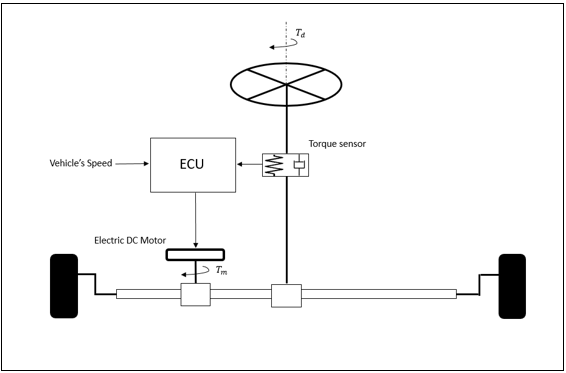
Figure 1.
- Electric Motor
- Electronic Control Unit
- Torque Sensor
Electric Motor
A simple electric DC motor is governed by two main dynamic equations:
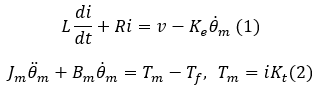
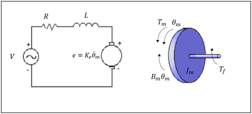
Figure 2.
where  and
and  are inertial and damping constants of the motor,
  and
and  are inductance and resistance of motor armature winding,
  is the armature current,
  and
and  are t he back EMF and torque constants of the motor,
  and
and  are the electromagnetic torque created by the motor and the counter balance torque acting
on motor shaft due to tire forces.
are the electromagnetic torque created by the motor and the counter balance torque acting
on motor shaft due to tire forces.
on pinion due to tires lateral force.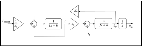
Figure 3.
- Activate motor part uses motor’s angular velocity to calculate the back EMF voltage
while with current value feedback the desired electrical torque is exported.
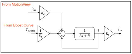
Figure 4. - MotionView motor part contains a body to represent motor’s
inertial properties and a rack and pinion coupler with the rack body to interact with
the system.
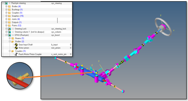
Figure 5.
| Parameter | Model | Default Value | Unit |
|---|---|---|---|
Inductance ( ) ) |
Activate | 9.06e-5 |  |
Resistance ( ) ) |
Activate | 0.0035 |  |
| Torque Coef. () |
Activate | 0.05285 | - |
| Back EMF Coef. () |
Activate | 0.05285 | - |
| Inertia () |
MotionView | 1000 |  |
The Activate diagram and the FMU used in MotionView model can be accessed from this location within the installation: <install_dir>\hwdesktop\hw\mdl\mdllib\Common\FMU_Library\EPAS\FMU_source
Torque Sensor
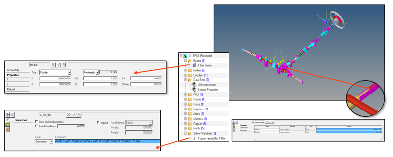
Figure 6.
| Parameter | Default Value | Unit |
|---|---|---|
| Young's Modulus (E) | 21000 |  |
| Shear Modulus (G) | 75000 | |
| Outer Diameter (OD) | 7 |  |
| Inner Diameter (ID) | 0 | |
| Damping Coef (CRatio) | 0.01 | - |
Boost Curve
 , increasing linearly until value
  which is reached when
 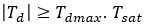 value is also decreasing linearly with the vehicle’s longitudinal
velocity in order to maintain vehicle’s stability and controllability. Driver’s input torque
value is also decreasing linearly with the vehicle’s longitudinal
velocity in order to maintain vehicle’s stability and controllability. Driver’s input torque
 and vehicle’s velocity
  are the plant output variables from vehicle’s model in MotionView.
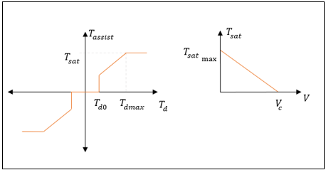
Figure 7.
| Parameter | Default Value | Unit |
|---|---|---|
Driver’s min torque ( ) ) |
1 |  |
Driver’s max torque ( ) ) |
8 | |
Motor max torque ( ) ) |
20 | |
Vehicle critical velocity ( ) ) |
100 |  |
Create a Full Vehicle Model with EPAS System
The MBD-Vehicle Dynamics Tools must be loaded as a preference file.
The Update Model utility is only available when the profile MBD-Vehicle Dynamics Tools is loaded. Follow the steps below to load this profile and access the utility:
-
From the Menu bar, select .
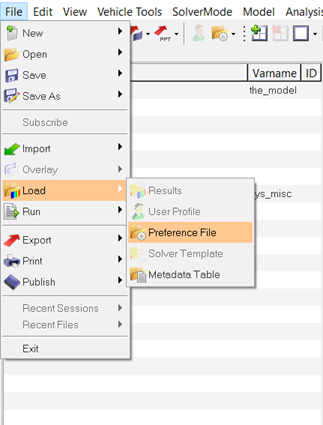
Figure 8. -
Choose the MBD-Vehicle Dynamics Tools profile and click
Load.
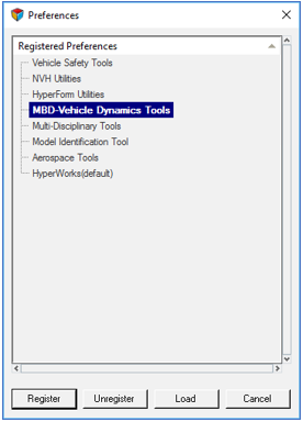
Figure 9. -
Click .
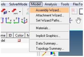
Figure 10. -
In the Model Type window, select the following:
-
In primary systems in order to add a power assisted steering system
Rackpin steering must be selected as steering
linkages.
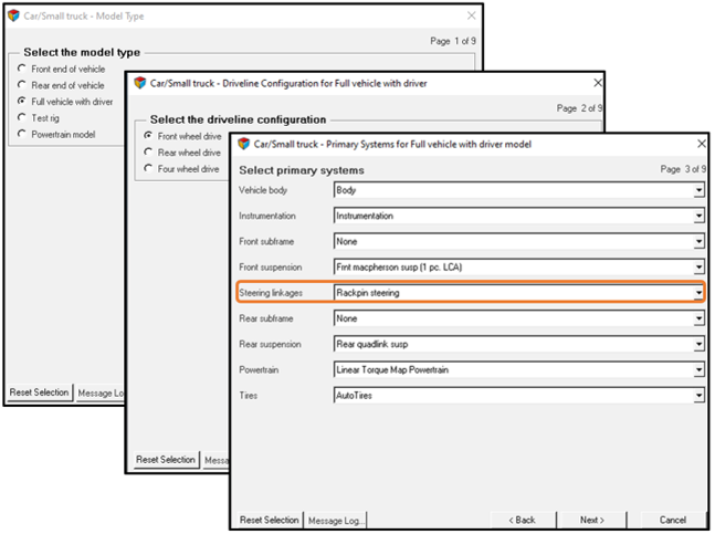
Figure 11.
-
In primary systems in order to add a power assisted steering system
Rackpin steering must be selected as steering
linkages.
-
In steering subsystems EPAS (Rackpin) will be available
as a Steering boost method.
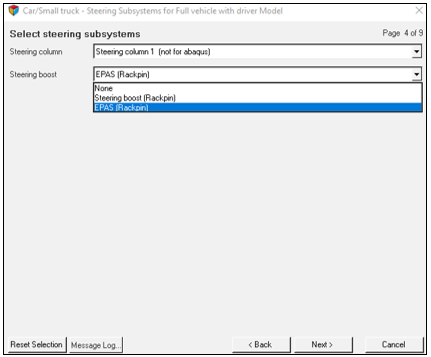
Figure 12.Other options for the model systems are left to your discretion.
Completing the Assembly Wizard’s selections will lead to a full vehicle model with Altair Driver and an Electric Power Assisted Steering System.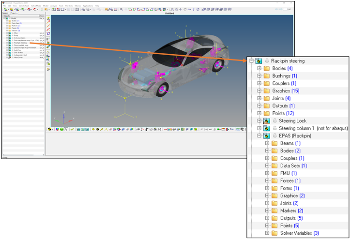
Figure 13.Steering maneuver simulation such as Sinusoidal Steering or Step Steer events can help you understand the behavior of an EPAS system. In the following diagrams these two events are presented for the displayed event settings and the results are compared with those of a vehicle with no steering boost system, performing the exact same maneuvers.
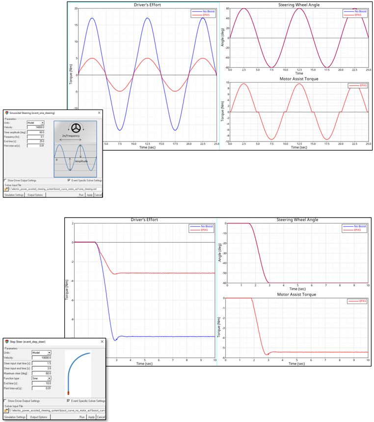
Figure 14.