Construct Models
MBS models can be created interactively in MotionView using its easy to use interface.
Add an Entity
- Click on the
icon in the Ribbon to bring up the Add “Entity” dialog.Attention: Points, Vectors, Joints, and Bushings are added using the guide bar in the modeling window (not the Add "Entity" dialog).
- Enter a Label and Variable for the entity.
- Click OK to add the entity and close the dialog.Tip: Click Apply to add the entity while retaining the dialog to add additional entities.
It is recommended to provide a meaningful Variable name (varname) to entities. Entities are identified and referenced through their variable names.
Edit an Entity
An entity can be selected by clicking on the entity in the browser or by clicking on the entity graphics (if available) in the modeling window.
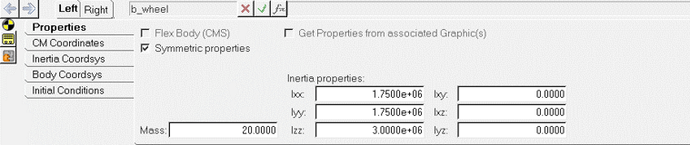
Figure 1.
- Real, Integer, String data
- File reference
- Drop-down option
- Entity reference
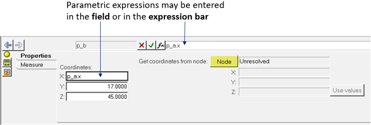
Figure 2.
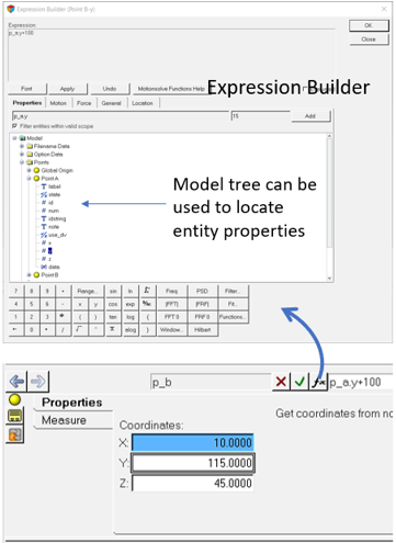
Figure 3.
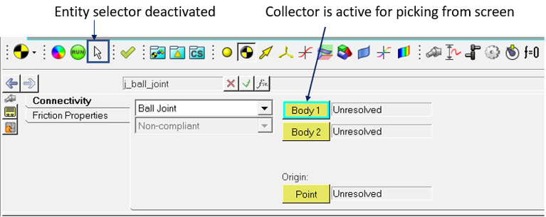
Figure 4.
- Picking the entity in the graphics area, if the entity has a graphical
representation.
OR
- Select dialog by clicking again (double-click) on the collector.
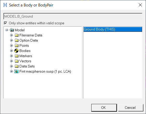
Figure 5.
Mouse and Keyboard Controls
| Press | To do this |
|---|---|
| Ctrl+Left mouse | Rotate the model. |
| Ctrl+Right mouse | Pan the model. |
| Ctrl+Scroll wheel | Zoom in/out. |
| 'F’ key | Fit the model to the window. |
Creating a multi-body model consists of creating entities such as bodies, points, graphics, joints, force elements and outputs. A CAD geometry can also be used as an input to create bodies and graphics.
Use CAD Geometry
MotionView supports reading several variety of CAD formats. CAD components can be imported to create bodies and associated graphics.
Interact with CAD geometry
MotionView can recognize features in the CADGraphics that may be used to create points and curves needed as reference for other entities. This feature needs to be turned on (off by default) from click the Preferences button to display the Options dialog and select Build Model.
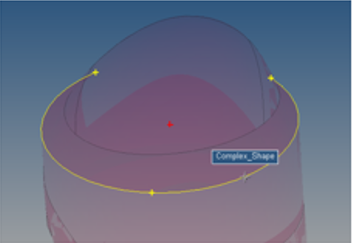
Figure 6.
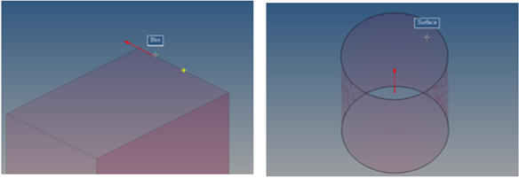
Figure 7.
To learn how to save and open models see the Opening and Saving a Model File topic.