Fix 2nd Order Mininodes

This macro improves element quality by moving the mid-edge nodes of second order elements.

You select the elements on which you want to improve the quality, and specify the quality constraints: Minimum Jacobian (evaluated at the corner nodes or integration points), Minimum Ratio between the minimum and maximum edge length, and Maximum angle.

Note: Moved midnodes are saved to your save list; this persists until you exit the program. In addition, moved midnodes lose any pre-existent association with the underlying geometry.

Typical usage of this utility begins with use of the Check Elems panel to identify poorly-formed elements, and using that panel’s save failed option. From that point onward, you use the Fix 2nd Order Midnodes utility.

  1. From the Utility Browser, Geom/Mesh menu, click Fix 2nd Order Mininodes.
    An element selector and proceed button display in the panel area.
  2. Click the elems selector and select retrieve to load the saved failed elements.
  3. Click proceed.
    The Fix 2nd Order Midnodes window opens. This pop-up window exists independently of the rest of the environment, so you can click-and-drag it to any desired location.
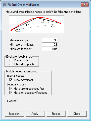

    Figure 1.
  4. In the Fix 2nd Order Midnodes dialog, choose your element quality constraints:
    1. Choose a Maximum angle.
      The utility will move midnodes such that the angle at the ends of each segment will not deviate from a straight line by more than this amount (thought of another way, the angle between the segments at the midnode will not exceed 180 degrees minus this value). See the figure above for an example using a value of 30 degrees.
    2. Specify a limit to the Aspect Ratio (minimum versus maximum length for the segments of the midnode-bearing edges).
      A value of 1 represents perfectly equal segment length, while a length of 0 would mean that the shorter segment might not exist, so this value must be greater than 0, but no greater than 1. Remember that this is a minimum ratio, so a value of 0.5 would allow the shorter segment to be half as long as the longer segment, or longer — but not shorter than half the length of the longer segment.
    3. Specify a Minimum Jacobian value and use the radio buttons to determine whether HyperMesh should evaluate each element’s Jacobian at the Corner nodes or the Integration points.
    4. To tell HyperMesh to keep the boundary nodes on the underlying model geometry but attempt to improve the Jacobian value by moving internal nodes, select the Allow movement checkbox.
    5. To allow nodes on geometry to move along (but not leave) the geometry features before any other node movement occurs, select the Move along geometry first checkbox.
    6. To allow HyperMesh to move boundary nodes off of the underlying geometry if a satisfactory Jacobian value cannot be achieved by moving along geometry or moving internal nodes, select the Move off geometry if needed checkbox.
      Note: This feature is always active when Allow movement is unchecked.
  5. Click one of the command buttons to perform an action:
    • Click Jacobian to check the current selected elements' Jacobian values and displays them in the results area..
    • Click Apply to tell HyperMesh to move the midnodes to try to match the criteria you specified..
    • Click Reject to undo any changes made when you clicked Apply
    • Click Close to close the Fix 2nd Order Midnodes dialog.
    When you click Apply, a message displays under the Results heading to inform you of exactly what HyperMesh did to the mesh. The images below illustrate the before-and-after state of a specific midnode and the criteria used, as well as the overall results:


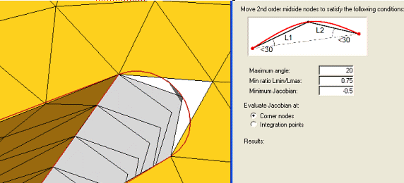
    Figure 2. Before Clicking Apply


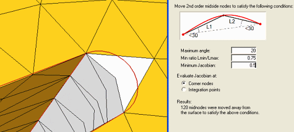
    Figure 3. After Clicking Apply