Assembly Browser
Use the Assembly Browser to manage parts and modules during the assembly building process.
From the menu bar, click .
Currently, Bill-of-Material (BOM) file support is limited to PLMXML assembly files from Teamcenter. For more details on the required Teamcenter configuration, supported PLMXML file formats, and supported transfer modes, contact your local Teamcenter support. Once the necessary configuration is made in Teamcenter, you can import the file in HyperMesh for representation management, batch meshing, connectors, and exporting the meshes and solver files.
The Assembly Browser structure is laid out in a table format. The different modules are displayed in the Entities column, and each module’s representation, material, PID, and thickness information is displayed in the columns that follow.
 .
.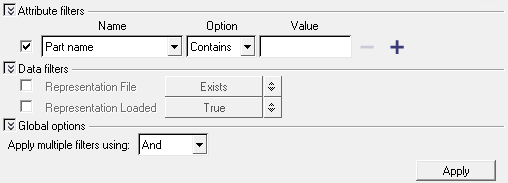
Figure 1.
To filter BOMs, apply the following advanced filters:
Apply Attribute Filters
Use these filters to determine, which Attribute(s) to filter upon.
- Optional:
To add an additional attribute filter, click
 .
.
- Optional:
To remove an attribute filter, click
 .
.
Apply Data Filters
Use these filters to determine what data appears in the Assembly Browser.
- To activate the Representation File filter, select its checkbox.
-
Click the Representation File toggle and select:
- Exists
- Does Not Exist
- To activate the Representation Loaded filter, select its checkbox.
-
Click the Representation Loaded toggle and select:
- True
- False
Apply Global Filters
- And:
- Or:
Assembly Browser Context Menu
Access advanced Assembly Browser options from the context menu when you right-click on a module in the browser.
Load BOM
PLMXML is the exchange format that transports the assembly information between Teamcenter and HyperMesh.
-
Right-click in the Assembly Browser and select
Load BOM from the context menu.
The XML Import dialog appears.
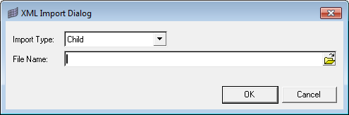
Figure 2.
Save WIP
To continue working with a saved UDMXML assembly BOM, load the WIP BOM using the Load BOM process. Select the saved WIP UDMXML BOM instead of the original PLMXML BOM.
Save PLMXML
In order to import the meshed parts into Teamcenter, an updated PLMXML .xml file is needed. This file captures any changes that were made to the assembly after it was imported into HyperMesh. If the original .xml file contained only CAD parts with thickness and material attributes, and if you meshed these parts in HyperMesh and made changes to the thickness for certain parts, then the delta PLMXML file will capture the changes made.
Set Rep
-
To change the representation of a module, right-click on the representation and
then select Set Rep from the context menu.
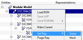
Figure 3.
Purge Rep
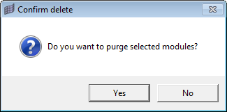
Figure 4.
HyperMesh will still maintain the representation in the hierarchy, and you can import when desired. When you purge a module, all of the changes you have made to the contents of the module will be lost permanently. HyperMesh will not automatically update the files in the current representation with the updated content. To retain the changes, you must save the modules as a HM file (or Solver file) before purging.
Import Rep
Set Param-Criteria
-
To set individual mesh parameter and criteria for selected module(s), select
Set Param-Criteria from the right-click context menu.
The Select Mesh Parameters & Criteria dialog appears.
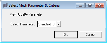
Figure 5.
Batchmesh
-
To batchmesh a module or modules, right-click on a module or modules and then
select Batchmesh from the context menu.
The Batchmesh Representation dialog appears.
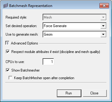
Figure 6. -
To start BatchMesher, click
Run.
The following messages appear during the batch mesh process:
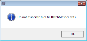
Figure 7. . Message displayed when BatchMesher is running in GUI mode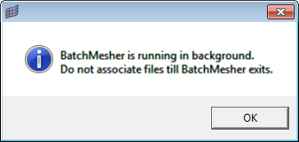
Figure 8. . Message shown when BatchMesher is running in background
Associate Mesh Files
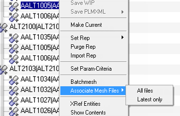
Figure 9.
The associate mesh file also searches the mesh files based on their extension and CAD file name. If HyperMesh associates the wrong mesh file, select and then locate the appropriate file.
Show Contents in Module
Export a Model
Show, Hide and Isolate Modules
Realize Connectors
-
To import and realize the connectors from a .mcf file,
click
 in the Assembly Browser.
The Mcf Import dialog opens.
in the Assembly Browser.
The Mcf Import dialog opens.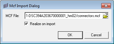
Figure 10.
Show All Attributes in a Module
Collapse and Expand All Modules in the Assembly Browser
To close all of the modules models in the tree structure and only display the top-most module, select Collapse All. To open all of the modules models in the entire tree structure and expose every item nested at every level, select Expand All.