Auto Connectors Macro
The Auto Connectors macro automates the importation and FE realization of connectors from either a Master Connectors File or an older Master Weld File.
Master Weld Files
The Master Weld File provides the weld location and parts to be connected.
Diameter vs. Thickness Files
The Diameter Table associates the thickness of flanges with spot weld diameters.
Example: Assign Flange Thickness Ranges and Spot Weld Diameters and Define Main Flange Thickness Settings
-
Click
 .
The Diameter Mapping dialog opens.
.
The Diameter Mapping dialog opens. -
Import or manually define flange thickness ranges and spot weld diameters in
the Diameter Table.
- To import predefined values, click from the menu bar.
-
To manually define values, click
 to add a row to the table. Default flange thickness ranges and spot
weld diameter values will be automatically interpolated. Edit these
values accordingly. To remove a range from the table, click
to add a row to the table. Default flange thickness ranges and spot
weld diameter values will be automatically interpolated. Edit these
values accordingly. To remove a range from the table, click  .
.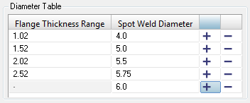
Figure 1.
-
For all flanges, define which flange thicknesses to consider when assigning
diameter values.
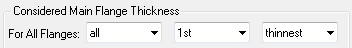
Figure 2. - Optional:
If you are connecting 2T, 3T, or 4T thicknesses, you can specify specific
flange thicknesses to consider when assigning diameter values to each
layer.
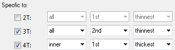
Figure 3.
Example
Consider there are five flanges with the following thicknesses:
Flange 1 = 3.0
Flange 2 = 1.5
Flange 3 = 1.0
Flange 4 = 2.0
Flange 5 = 2.5
In the Diameter Table below, four sets of flange thickness ranges and spot weld diameter values have been defined. Below the table, the options have been set to only consider and assign a spot weld diameter to the inner flange with the 2nd thinnest thickness. If there is two layer thicknesses, all of the flanges will be considered, but only the 1st thickest flange will be assigned a spot weld diameter. In this example, there is only one layer.
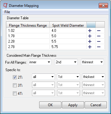
Figure 4.
ACM Welds
An ACM (Area Contact Method) weld is a special representation of a spot weld.
The weld is defined using a solid (HEXA) element whose cross-sectional area is equivalent to the area of the weld nugget. The solid element is created at the exact weld location independent of the shell elements that represent the sheet metal parts. These solid elements are connected to the corresponding components using RBE3 elements. The size of the solid element is determined using the Diameter Table or using a specific value that you specify in the Spot panel. The spot weld diameter corresponding to the thickness ranges of the connecting flanges is obtained from the Diameter Table. The size of the hexa is calculated to match the cross-sectional area of the weld nugget.
- (T1 + T2)/2
- This creates the hexa elements with a length equal to the average component thickness it is connecting. T1 and T2 are the component thicknesses. The first figure below shows the ACM weld created using this method.
- Project to shell
- This creates the hexa elements between the component/element shell surface. The length of the hexa element will be equal to the actual distance between the two connecting components/elements. The second figure below shows the ACM weld created using this method.
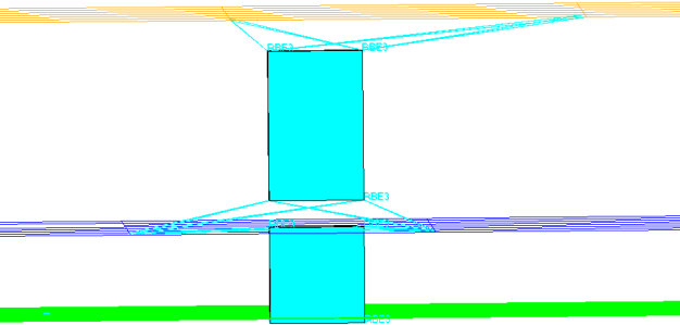
Figure 5. ACM Creation using (T1+T2)/2.0
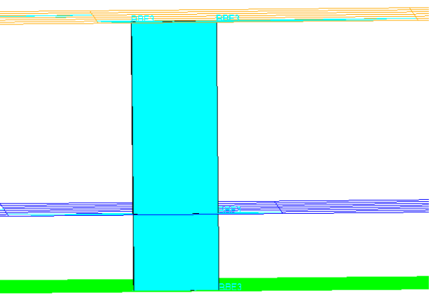
Figure 6. ACM Creation using Project to Shell
The weights of the RBE3 elements are calculated based on the projection of the dependent node on the shell element. The nodes of the shell element closest to the dependent node are assigned a greater weight relative to the node that is farther away.
Realize ACM Spotwelds
ACM welds can be created and managed using connectors. Once a connector is created, they can be realized as ACM spotwelds.
CWELD Elements
CWELD elements are created as patch-patch, meshless elements.
The 1D element is not connected to the shell element. For details regarding connected shell elements or nodal information see the element card.
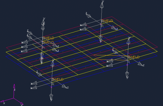
Figure 7.