Connector Entity Browser
The middle section of the Connector Browser contains a tree view of all the connections contained in the model, and has its own set of tools similar to the ones found in the Link Entity Browser.
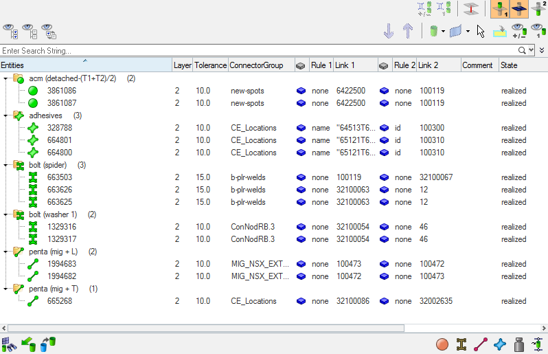
Figure 1.
The connector information in the tree can be used to find link entities connected by specific connectors, and also to modify certain connector attributes. The columns display a sub-set of connector information that is important for recognizing connection information easily.
- General – all of the links are within the same subsystem
- Subsystem – one or all of the links are in multiple subsystems
- Attachment – a new single lined connector entity
Unless all view option toggle buttons in the global display tool set are inactive, the action mode tool set and the context menu actions (show, hide, isolate, isolate only) work similarly to their functions in the Model Browser's component view.
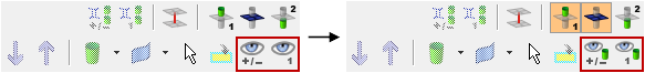
Figure 2.
- 1st connector entity
- Selected connectors.
- linked entities
- Links which are referenced by one of the selected connectors.
- 2nd connector entity
- Connectors which reference at least one of the linked entities.
This kind of categorical separation is only used for the actions show, hide, isolate and isolate only, and only when one of the view option toggle buttons is active, regardless of whether the actions are taken from the context menu or the action buttons. No other functionality uses this categorization at all.
You can also change the base features of the Connector Entity Browser in the Connector Entity Browser configuration window.
| Option | Description |
|---|---|
| Entities | ID of the connector and an image that represents the respective connector’s style (spot, seam, bolt, and so on). |
| Status | Realization state of the connector entity:
unrealized, realized,
failed, or
modified. Note: For those writing scripts
instead of using the GUI, a more detailed report can be
created by using the following lines in your script: set
error_report [ hm_ce_errorreport CE_ID 1 ].
|
| Tolerance | Realization tolerance of the connector. You can change this by right-clicking the field and typing in a new value, then pressing Enter. |
| Type of entity that can be added to the selected connector(s)
as a link reference. Supported entities are assemblies,
components, surfaces, elements, tags, and nodes. Tip: Left-click on a link to highlight the relevant entity
(part) in the graphics area.
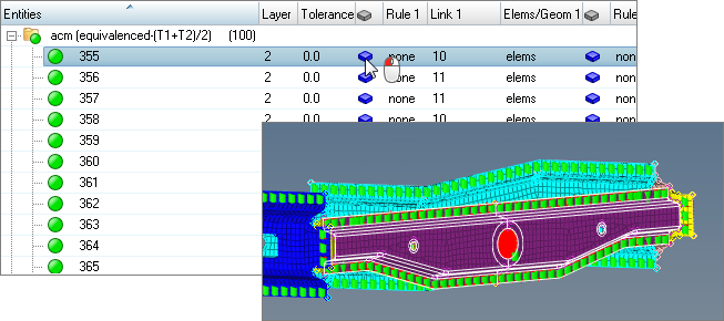 Figure 3. |
|
| Rule | Defines how a connector treats an entity added as a link. Adding a link with an ID or name rule forces the connector to retain the link’s ID or name even if that link entity no longer exists in the database. This aids in part replacement when a new part replaces an old part and both share the same ID or name. Adding a link with the at fe-realize rule ensures that each time a connector is realized the closest entity of the correct type is found and connected. This is useful when connectors need to connect to a closest part in an assembly. |
| Link | ID or name of the entity added as a link to a connector. |
| Layer | Total number of link entities to be joined by the connector. This is also marked as thickness layers (2T/3T/4T, and so on). |
| Subsystem | Displays connectors associated with a subsystem. |
| Connector Group | Name of the Connector Group to which the connector belongs. |
| Comment | Input comments for a connector. |
| Error Message | Error messages for a connector. |
Functionality is accessed from the global display tool set, an action modes tool set and a right-click context menu.