HM-3140: Batch Meshing
BatchMesher is a tool that can perform geometry cleanup and automeshing (in batch mode) for given CAD files. BatchMesher performs a variety of geometry cleanup operations to improve the quality of the mesh created for the selected element size and type. Cleanup operations include: equivalencing of "red" free edges, fixing small surfaces (relative to the element size), and detecting features.
BatchMesher also performs specified surface editing/defeaturing operations such as: removal of pinholes (less than specified size), removal of edge fillets, and addition of a layer of washer elements around holes.
All user-defined criteria determines the quality index (QI) of a model. The QI value is used to assess the potential of each geometry cleanup and meshing tool, and apply them accordingly. QI optimized meshing and node placement optimization are performed to obtain the best quality meshing. Final results are stored in a HyperMesh database file.
- Define a configuration for the batch mesh
- Edit the criteria and parameter files
- Set up a simple user procedure for a post-batch mesh run
- part1.hm
- part2.hm
- bm_housing.hm
- bm_housing.criteria
- bm_housing.param
- bm_housing.tcl
Start BatchMesher
In this step you will start BatchMesher.
-
In the Input model directory field, click
 and
navigate to your working directory.
Note: In this exercise you will use files located in the hm.zip file.
and
navigate to your working directory.
Note: In this exercise you will use files located in the hm.zip file. -
In the Output directory, click and
navigate to the appropriate directory if different from the Input model
directory.
-
On the right-hand side of BatchMesher, click
 .
The Select Model Files dialog appears.
.
The Select Model Files dialog appears.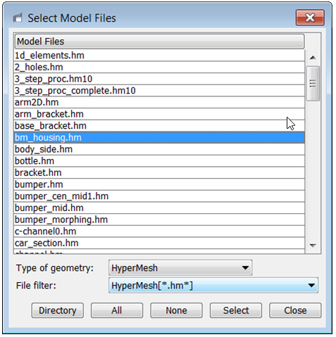
Figure 1.
Define a Configuration for the Batch Mesh Run
In this step you will define a configuration for the batch mesh run.
-
Click the Configurations tab.
BatchMesh displays several common configurations already available.
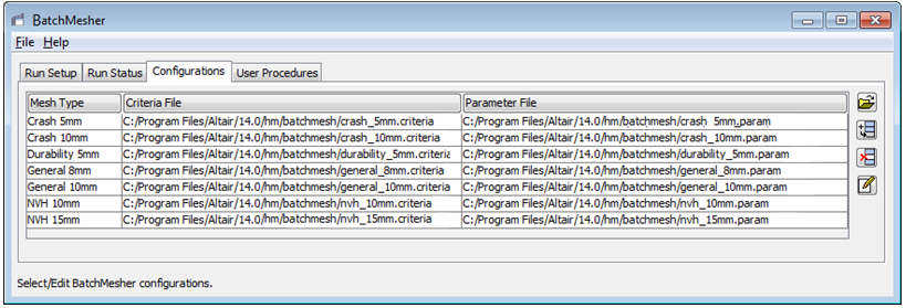
Figure 2. -
On the right-hand side of BatchMesher, click
 .
BatchMesher adds a new entry to the table of configurations.
.
BatchMesher adds a new entry to the table of configurations. -
Double-click the Criteria File field and then click
.
-
Double-click the Parameter File field and then click
.
Set Up a Simple Script
In this step you will set up a simple script to perform a tetramesh on the housing.
-
On the right-hand side of BatchMesher, click .
BatchMesher adds a new entry to the table of user procedures.
-
Double-click the TCL File field and then click .
-
Double-click the Name field and then type a name for the
procedure. For example, tetmesh.
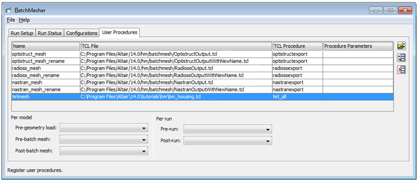
Figure 3.
Define a Configuration Using Run Setup
In this step you will begin defining a configuration for the batch mesh run using the run setup tab.
-
For the geometry file,
bm_housing.hm, click the Post-Mesh field and select the procedure you created in Step 3.Note: This will run the tetramesher on all available shell elements after batch meshing.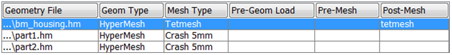
Figure 4. -
Obtain more details on a single job when its status is Working by selecting the
job and then clicking Show Details.
A detailed summary appears with a table containing information about the model during each step of the batch meshing process, such as the number of failed elements and the quality index.
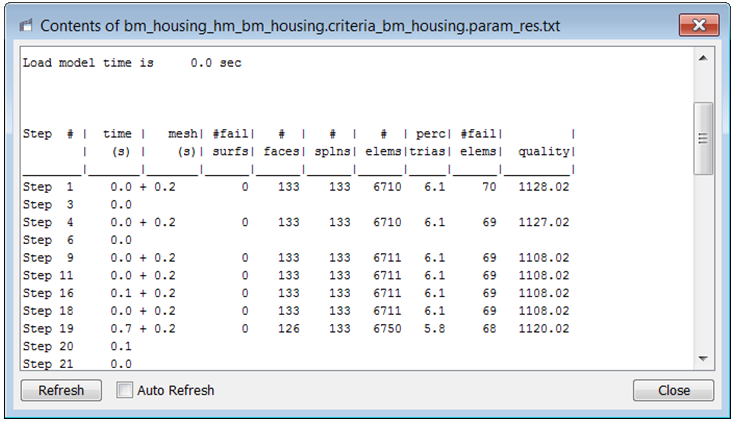
Figure 5.
Edit the Criteria and Parameter Files
In this optional step you will edit the criteria and parameter files.
-
Right-click on the Criteria File or Parameter
File field that you wish to edit and select Edit
File from the context menu.
The Criteria and Parameters Files Editor dialog appears.
- From the Criteria tab, you can set the target element size, element criteria, and the method that is used to calculate the values. You can also select the Advanced Criteria Table check box to enabled additional options that give you more control over the intermediate QI values, however, it is usually not necessary to edit these options in order to obtain a good quality mesh. The Use min length from timestep calculator check box is also available for explicit solver models. If you select this check box, the overall minimum element size will be set by this option and the top element checks will be disabled.
- From the Parameters tab, you can set all of the meshing controls over
various geometric features. Parameters are grouped into sections; you
can click the small downward-arrows next to each section to show and
hide that section. The number of parameters is extensive; for more
details, see the Parameters Editor topic in the BatchMesher help.
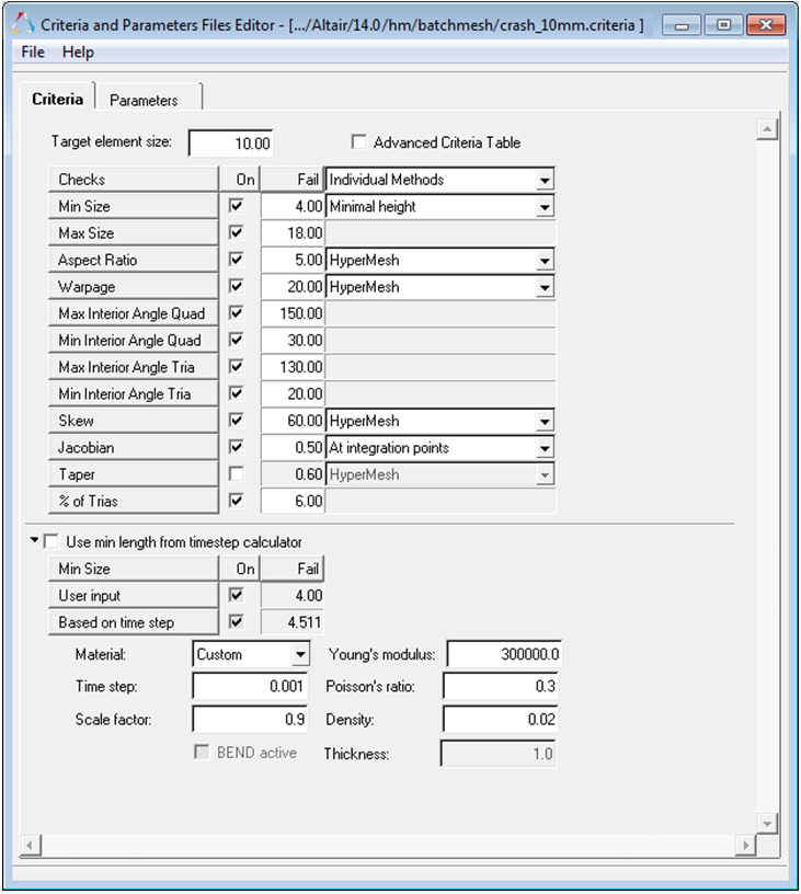
Figure 6.