HM: 3110: Mesh Without Surfaces
Surfaceless meshing is defined as the creation of mesh using points, lines, and nodes rather than surfaces. Some parts may have missing surfaces and some parts may not have any surfaces at all and are instead defined by line data. Either way, a mesh still must be created. HyperMesh has a number of panels that you can use to create a mesh based on geometry rather than surfaces.
- The basic concepts of surfaceless meshing and how to mesh a bracket
- Scale (Uniform scaling)
- 2D mesh by using spline, line drag, and skin
- Ruled mesh
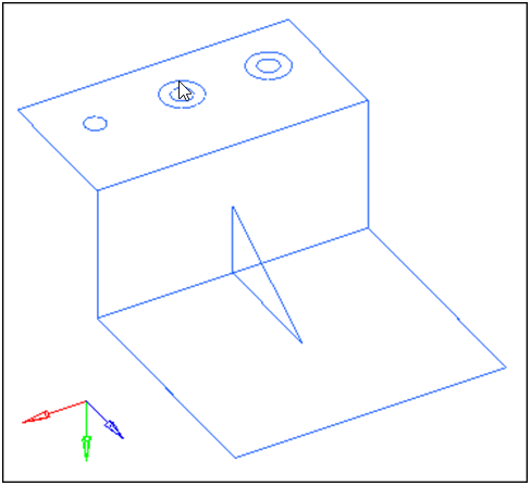
Figure 1.
Open the Model File
In this step you will open the model file, bracket.hm.
- Start HyperMesh Desktop.
- From the menu bar, click .
- In the Open Model dialog, open the bracket.hm model file.
- Observe the model using the differnet visual options available in HyperMesh, such as rotation and zoom.
Create a Concentric Circle Using the Scale Panel
In this step you will create a concentric circle around a hole on the top face using the Scale panel.
There are three circles on the upper region of the bracket, which represent three holes in the bracket. Two of the holes have concentric circles around them. This configuration allows you to create a radial mesh pattern around the holes. The following steps will show you how to create a concentric circle around the third hole.
-
Press and hold your left mouse button, move it over the circle representing the
hole as indicated in the following image, and then release it when the cursor
changes to a square with a dot in the center
 .
.
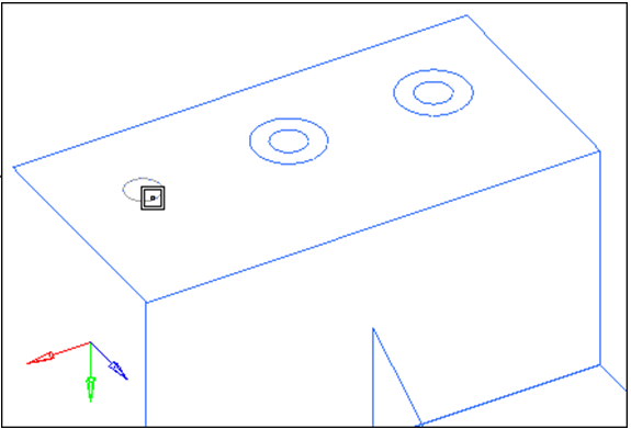
Figure 2.HyperMesh highlights the circle. -
Click circle center.
A node is created at the circle's center.Note: This node will be selected as the origin node when the circle is duplicated and scaled.
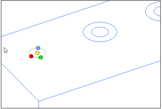
Figure 3.
Create a Radial Mesh Using the Spline Panel
In this step you will create a radial mesh between each of the concentric circles using the Spline panel.
-
Select all six circular lines.
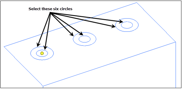
Figure 4. -
Click mesh.
The preview mesh is updated based on the change.
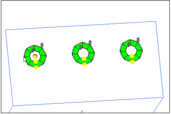
Figure 5.
Mesh Using the Spline Panel
In this step you will mesh the rest of the top face using the Spline panel.
-
To accept the mesh and go back to the main menu, click
return twice.
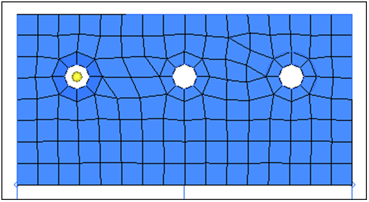
Figure 6.
Mesh Using the Line Drag Panel
In this step you will mesh the back face of the bracket using the Line Drag panel.
-
Select the line that is on the perimeter of the existing mesh and adjacent to
the bracket's back face as indicated in the following image.
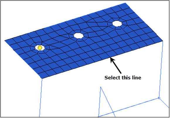
Figure 7. -
Select one of the two lines defining the back face that are perpendicular to
the selected line to drag as indicated in the following image.
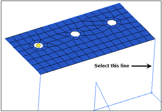
Figure 8. -
To accept the mesh and return to the main menu, click
return twice.
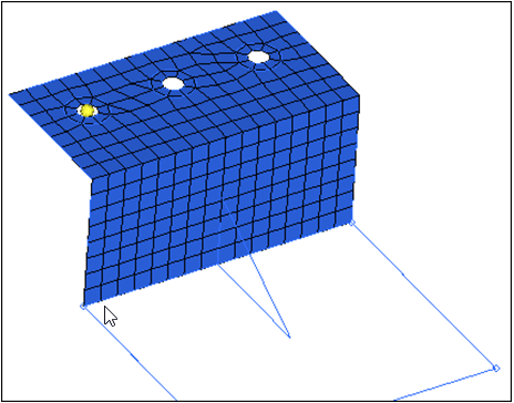
Figure 9.
Mesh Using the Ruled Panel
In this step you will mesh the bottom face of the bracket using the Ruled panel.
-
Select the end nodes located on the back face edge that borders the bottom
face, as indicated in the following image.
All nodes between the two selected nodes are selected.
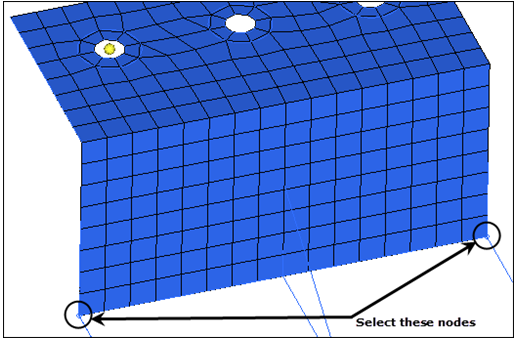
Figure 10. -
Select the line defining the opposite edge of the bottom face as indicated in
the following image.
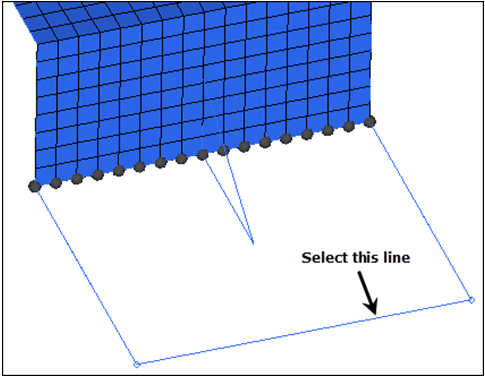
Figure 11. -
To accept the mesh and return to the main menu, click
return twice.
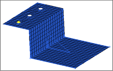
Figure 12.
Mesh Using the Skin Panel
In this step you will mesh the rib using the Skin panel.
-
To accept the mesh and return to the main menu, click
return twice.
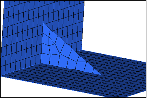
Figure 13.