HM-3100: AutoMesh
The optimal starting point for creating a shell mesh for a part is to have geometry surfaces defining the part. The most efficient method for creating a mesh representing the part includes using the Automesh panel and creating a mesh directly on the part’s surfaces.
- Learn how to mesh all surfaces at once, specifying different element sizes and element types
- Practice changing the element density along surface edges
- Practice checking element quality and changing the mesh pattern by changing the mesh algorithm
- Learn how to preview the mesh on all the unmeshed surfaces
- Practice changing the element type and node spacing (biasing) along surface edges
- Learn how to remesh surfaces
This exercise uses the channel.hm file, which can be found in the hm.zip file. Copy the file from this directory to your working directory.
Open the Model File
In this step you will open and view the model file, channel.hm.
- Start HyperMesh Desktop.
- From the menu bar, click .
- In the Open Model dialog, open the channel.hm model file.
- Observe the model using the different visual options available in HyperMesh, such as rotation and zooming.
Mesh Part Surfaces
In this step you will mesh part surfaces all at once using an element size of 5 and mixed element types, quads and trias.
Delete the Mesh
In this step you will delete the mesh.
-
To open the Delete panel, click
 on the
Collectors toolbar, or press F2.
on the
Collectors toolbar, or press F2.
- Set the entity selector to elems.
- Click elems >> all.
- Click delete entity.
- To go back to the AutoMesh panel, click return.
Mesh with Three Fixed Points
In this step you will mesh the surface having three fixed points interior to its surface.
You should be in the AutoMesh panel, size and bias subpanel.
-
Select the surface that has three fixed points interior to its surface as
indicated in the following image.
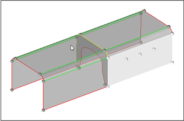
Figure 1.
Fit Meshed Surface to Graphics Area
In this step you will fit the surface to the graphics area.
Specify a New Element Density
In this step you will specify a new element density along surface edges.
-
To change the element density number of the edge indicated in the following
image from 24 to 48:
- Left-click on the edge's element density number to increase it by one, or right-click on the element's density number to decrease it by one, or
- Click and hold the mouse pointer on the edge's element density number
and drag your mouse up to increase the number or down to decrease the
number.
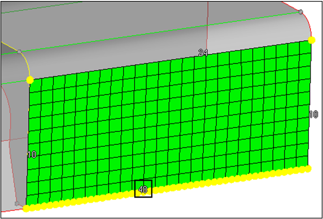
Figure 2.
-
Click mesh.
HyperMesh updates the preview mesh based on the change.
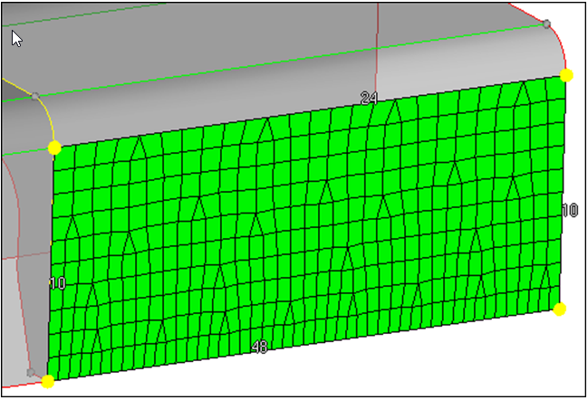
Figure 3.
Specify a New Element Density along Surface Edges
In this step you will specify a new element density along surface edges.
You should still be in the density subpanel.
-
Select the element density number of the edge indicated in the following image
to change its value to 10.
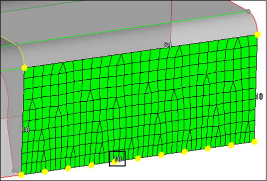
Figure 4. -
Click set all to.
HyperMesh changes all the edge densities to 10.
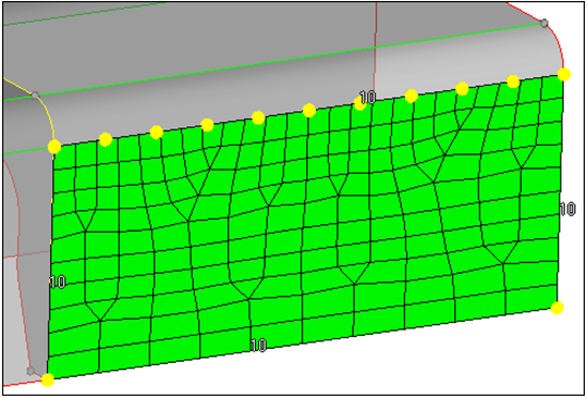
Figure 5.
Adjust Element Densities
In this step you will specify a new element size to adjust element densities along surface edges.
You should still be in the density subpanel.
-
Select the element density number of the edge indicated in the following image
to calculate it based on an element size of 7.
HyperMesh calculates the new number to create elements as close as possible to 7.
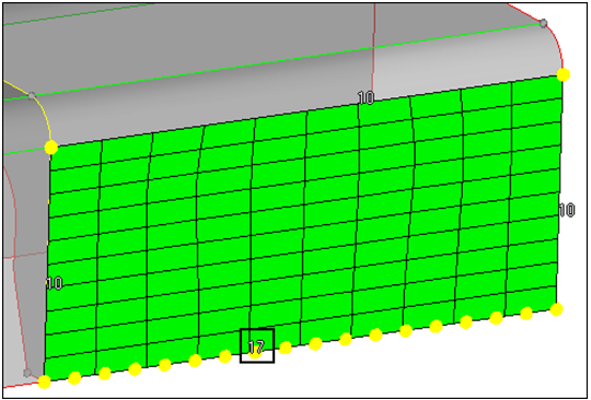
Figure 6. -
Click mesh.
HyperMesh updates the preview mesh based on the change.
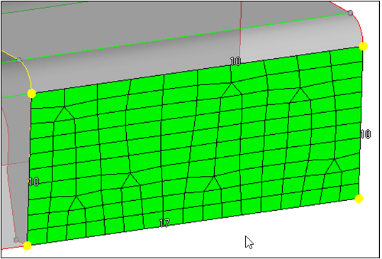
Figure 7. -
Click mesh.
HyperMesh updates the preview mesh based on the change.
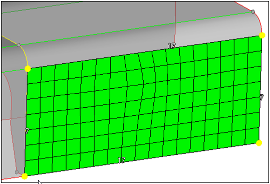
Figure 8.
Change All Edge Element Densities
In this step you will change all edge element densities to reflect the initial element size of 5.
Preview a Mesh of the Channel Rib
In this step you will preview a mesh of the channel's rib.
You should still be in the Mesh panel, size and bias subpanel.
-
With the entity selector active and set to surfs, select the rib surface in the
middle of the part as indicated in the following image.
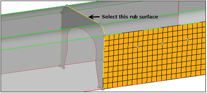
Figure 9. -
To fit the rib's surface to the graphics area, click local view >>
rear.
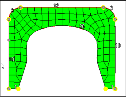
Figure 10.
Check the Mesh Quality
In this step you will check the quality of the rib's preview mesh.
-
To identify all of the elements that have a jacobian less than 0.8, click
jacobian.
HyperMesh identifies several elements that fail the check and outlines them in red. The status bar reads, "Minimum jacobian found is equal to 0.75."
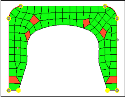
Figure 11.
Change the Rib Mesh Pattern
In this step you will change the rib's mesh pattern by changing the mesh method used for its surface.
-
Go to the mesh style subpanel. The edge's element density numbers have
disappeared, and there is now a small icon interior to the rib's surface. This
icon indicates that HyperMesh is currently using the
free (unmapped) mesh method to mesh the surface.
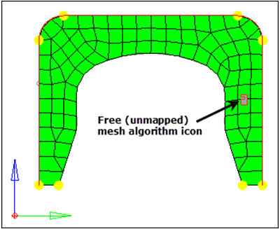
Figure 12. -
Click mesh.
HyperMesh updates the preview mesh based on the change.
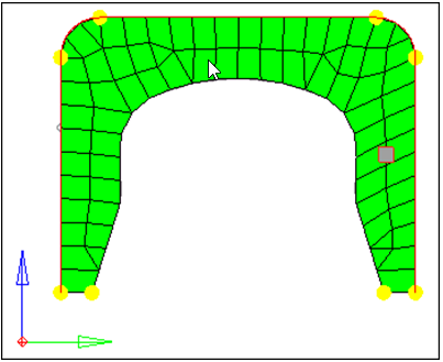
Figure 13.
Check Rib Preview Mesh Quality
In this step you will check the quality of the rib's preview mesh again.
- Go to the checks subpanel.
- Check for elements having an aspect ratio greater than 5. What is the highest value reported?
- Check for elements having a jacobian less than 0.7. What is the lowest value reported? In this case, the free (unmapped) mesh has a better jacobian than the map as rectangle mesh.
- Check for quad elements having a min angle less than 45. What is the smallest value reported?
- Check for quad elements having a max angle greater than 135. What is the highest value reported?
Change the Mesh Method to Free (Unmapped)
In this step you will change the rib's mesh method back to free (unmapped).
Preview Displayed Unmeshed Surfaces
In this step you will preview a mesh of all displayed, unmeshed surfaces.
You should still be in the Mesh panel, size and bias subpanel.
-
On the Standard toolbar, click
 .
.
-
Click mesh.
HyperMesh opens the meshing module and generates the preview mesh.
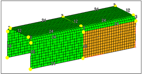
Figure 14.
Change the Element Type to Trias
In this step you will change the element type for some surfaces to trias.
-
Under elem type, click toggle surf.
HyperMesh displays
 interior to each surface, which indicates that the
mixed element type (quads and trias) is currently being used to mesh the
surface.
interior to each surface, which indicates that the
mixed element type (quads and trias) is currently being used to mesh the
surface. -
On the two surfaces indicated in the following image, left-click on to set their element type to trias (
 ).
).
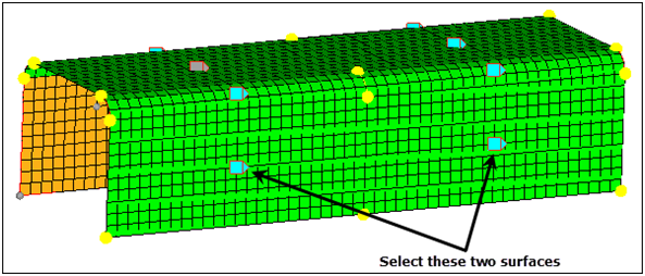
Figure 15. -
Click mesh.
HyperMesh updates the preview mesh based on the change.
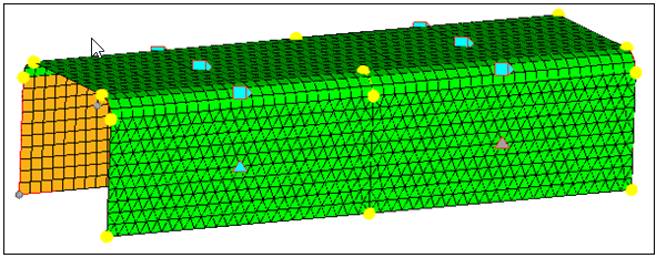
Figure 16.
Adjust Node Spacing
In this step you will adjust the node spacing on surface edge (biasing).
-
To change the biasing intensity number of the edge indicated in the following
image from 0.0 to 3.0:
- Left-click on the edge’s biasing intensity number to increase it by 0.1, or right-click on the edge's biasing intensity number to decrease it by 0.1, or
- Click and hold the mouse pointer on the edge’s biasing intensity number
and drag your mouse up to increase the number or down to decrease the
number.
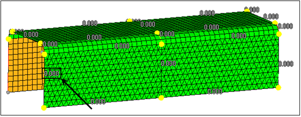
Figure 17.
-
Click mesh.
HyperMesh updates the preview mesh based on the change.
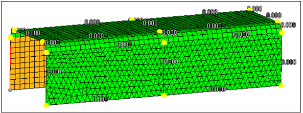
Figure 18. -
On the same edge, click
 to change it from the linear bias style to the bellcurve (
 ) bias style.
Remesh the Bottom Two Surfaces
In this step you will remesh the channel's bottom two surfaces.
You should still be in the Mesh panel, size and bias subpanel.
-
Select the two surfaces as indicated in the following image.
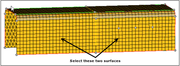
Figure 19.
Save Your Work
In this step you will save your work.
This step is optional.