Generate Comparison Results
In the Generate tab, define the following options, which will be used to generate the comparison results.
-
From the Location list, specify where the entities you are comparing can be
found.
- Choose Auto to generate results for entities positioned at any location, by automatically calculating a transformation matrix between the source and target entities. A maximum of one match for each source entity will be found. This option is only available for CAD-CAD comparison.
- Choose Position to generate results for entities positioned at a location that you specify. For the Source entities and the Target entities collectors, select up to three locations on the source that correspond to the same three locations on the target. This option will use these locations to define the transformation of the source entities to the target entities. A maximum of one match for each source entity can be found.
- Choose Recursive to generate results for entities positioned at any location, by automatically calculating transformation matrices between the source and target entities. Multiple matches can be found for each source entity. A source entity may match more than one target entity positioned at a different location. This option is only available for CAD-CAD comparison.
- Choose Rotate to generate results for entities rotated
about a vector. Multiple matches may be found for each source entity, depending:
- Axis
- Select a collector that defines the rotation axis/vector.
- Angle
- Specify the rotation angle to search and find target entities.
- Steps
- Specify the number of times to increment the angle value when searching.
- For example, in the image below, assume the red element is the source, the blue
elements are the target, and the z-axis is the rotation vector. If the angle = 60
and the steps = 1, then only the first blue element will be found. If the steps =
2, then the first two blue elements will be found. If the steps = 3, then all
three blue elements will be found. Similarly, if the angle = 30 and the steps = 1,
then no blue elements will be found, but if the steps = 2, then the first blue
element will be found.
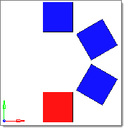
Figure 1.
- Choose Same side to generate results for entities positioned at the same location. A maximum of one match can be found for each entity source.
- Choose Symmetry to generate results for entities positioned symmetrically about a plane. A maximum of one match can be found for each source entity. When you select this option, the Symmetry plane selector becomes active. Use the Symmetry plane selector to select the plane about which the symmetry exists.
- Choose Translate to generate results for the entities
translated along a vector. Multiple matches may be found for each source entity,
depending on:
- Direction
- Select a collector that defines the translation vector.
- Distance
- Specify the translation distance to search and find target entities.
- Steps
- Specify the number of times to increment the distance value when searching.
- For example, in the below image, assume the red element is the source, the blue
elements are the target, and the x-axis is the direction vector. If the distance =
2 and the steps = 1, then only the first blue element will be found. If the steps
= 2, then the first two blue elements will be found. If the steps = 3, then all
three blue elements will be found. Similarly, if the distance = 1 and the steps =
1, then no blue elements will be found, but if the steps = 2, then the first blue
element will be found.
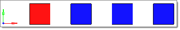
Figure 2.
- Optional:
Perform a comparison a shells using their thickness.
-
Use the Ignore holes/slots option to specify which holes and/or slots in the
surface data to ignored during the comparison.
If the features are smaller than the specified Holt/slot diameter and/or Slot length criteria, then they will be ignored. Element edges in the region of an ignored hole or slot are not required to be within the tolerance of a surface line. Element nodes over an ignored hole or slot cannot cause the element to be marked as intersected.
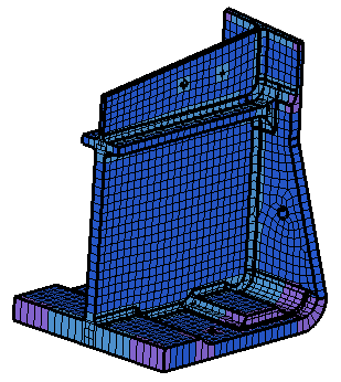
Figure 3.
-
Use the Ignore holes/slots option to specify which holes and/or slots in the
surface data to ignored during the comparison.
Comparison Result Types
Overview of the different result types you can select when working with the Comparison tool.
Standard Comparison
| CAD-CAD | CAD-FE/FE-CAD | FE-FE | |
|---|---|---|---|
| Basic | Matched (paired) Unmatched |
Matched (paired) Unmatched |
Matched Unmatched |
| Full | Matched
(paired) Overlapped Intersected Unmatched |
Matched
(paired) Overlapped Intersected Unmatched |
Matched
Overlapped Intersected Unmatched |
| Detailed | Matched (paired) Overlapped (paired) Intersected (paired) Unmatched |
Matched (paired) Overlapped (paired) Intersected (paired) Unmatched |
Matched Overlapped Intersected Unmatched |
- CAD-CAD
-
Result Type Description Basic - Matched
- Occurs when a source or target surface is within the given tolerance of a compared surface using a direct surface to surface comparison. All points and lines comprising each surface must match between the surfaces. Each matched surface is placed in a separate match type group with the surface it matches.
- Unmatched
- Occurs when a source or target surface differs from the closest compared surface to a degree larger than the tolerance.
Full - Matched
- Occurs when a source or target surface is within the given tolerance of a compared surface using a direct surface to surface comparison. All points and lines comprising each surface must match between the surfaces. Each matched surface is placed in a separate match type group with the surface it matches.
- Overlapped
- Occurs when all facet nodes of a source or target surface are within the given tolerance of the compared surfaces and all of the facet nodes on the nearest compared surfaces' exterior edges are within the given tolerance of the source or target surface's exterior edges. All of the overlapped surfaces are placed in a single match type group.
- Intersected
- Occurs when at least one but not all facet nodes on a source or target surface are within the given tolerance of the compared surfaces or at least one of the facet nodes on the nearest compared surfaces' exterior edges is outside the given tolerance of the source or target surface's exterior edges. All of the intersected surfaces are placed in a single match type group
- Unmatched
- Occurs when there are no facet nodes on a source or target surface that are within the given tolerance of the compared surfaces, or all the criteria for the intersected match type are met and no interior facet nodes for the surface are within the tolerance of the compared surfaces.
Detailed Behaves the same as Full, except overlapped and intersected match types are separated out into pairs, or contiguous groups which share the same match type. - CAD-FE/FE-CAD
-
Result Type Description Basic - Matched
- Occurs when a group of elements are found having all nodes within the given tolerance of a surface, the areas defined by the surface and the elements are within 3%, and all of the nodes on the elements' exterior edges are within the given tolerance of the surface's exterior edges. Each matched surface is placed in a separate match type group with the elements it matches.
- Unmatched
- Occurs for surfaces and elements when the matched criteria are not met.
Full - Matched
- Occurs when a group of elements are found having all nodes within the given tolerance of a surface, the areas defined by the surface and the elements are within 3%, and all of the nodes on the elements' exterior edges are within the given tolerance of the surface's exterior edges. Each matched surface is placed in a separate match type group with the elements it matches.
- Overlapped
- Occurs for a surface when all facet nodes on the surface are within the given tolerance of the elements and all nodes along the nearest FE mesh's exterior edges are within the given tolerance of the surface's exterior edges. It occurs for an element when all of the nodes of the element are within the given tolerance of the surfaces and all of the nodes of the element which touch the FE mesh’s exterior edges are within the given tolerance of the surfaces’ exterior edges. All overlapped surfaces and elements are placed in a single match type group.
- Intersected
- Occurs for a surface when at least one of the facet nodes on the surface is within the given tolerance of the elements and at least one point along the nearest FE mesh's exterior edges is outside the given tolerance of the surface's exterior edges. It occurs for an element when at least one node of the element is outside the given tolerance of the surfaces, or when at least one of its nodes which touch the FE mesh’s exterior edges is outside the given tolerance of the surfaces’ exterior edges. All of the intersected surfaces and elements are placed in a single match type group.
- Unmatched
- Occurs for a surface when there are no facet nodes on the surface that are within the given tolerance of the elements. It occurs for an element when no nodes of the element are within the given tolerance of the surfaces.
Detailed Behaves the same as Full, except that each surface will be placed in a separate match type group with the elements it overlaps or intersects with. Due to the grouping process, surfaces that are not grouped with any elements are marked as unmatched. In Full results, such surfaces may be marked as intersected if a surface edge is within the given tolerance of an element but there is no overlap in the interior of either. A given surface may be in two match type groups: one with overlapped elements and another with intersected elements. - FE-FE
-
Result Type Description Basic - Matched
- Occurs when an element is within the given tolerance of another element using a direct node to node comparison. All matched elements are placed in a single match type group.
- Unmatched
- Occurs if at least one node for the element lies outside the given tolerance of the nodes of the compared FE mesh.
Full - Matched
- Occurs when an element is within the given tolerance of another element using a direct node to node comparison. All matched elements are placed in a single match type group.
- Overlapped
- Occurs when all nodes of a source or target element are within the given tolerance of the compared elements and all of the element’s nodes which touch the FE mesh’s exterior edges are within the given tolerance of compared FE mesh’s exterior edges. All of the overlapped elements are placed in a single match type group.
- Intersected
- Occurs when at least one node of a source or target element is outside the given tolerance of the compared elements or at least one of the element’s nodes which touches the FE mesh’s exterior edges is outside the given tolerance of the compared FE mesh’s exterior edges. All of the intersected elements are placed in a single match type group.
- Unmatched
- Occurs when there are no nodes of a source or target element that are within the given tolerance of the compared elements.
Detailed Behaves the same as Full.
Thickened Shell Comparison
When you are performing a thickened shell comparison, Basic, Full, and Detailed all
produce the same answer.
- CAD
-
- Matched
- There is no criteria for matched surfaces in a thickened shell comparison. However, a value is provided by dividing the matched FE area by two. Surfaces are set to 100% matched if the FE is also 100% matched. Surfaces are never categorized as matched, though, as the overlapped match type is the maximum category.
- Overlapped
- Occurs when all points of a surface are within the tolerance of the elements (when offset is projected by thickness). The element edge nodes that are not within the tolerance of a surface edge may be projected on to the surface. This is calculated by dividing the overlapped FE area by two.
- Intersected
- Occurs when at least one point of a surface is within the tolerance of the elements (when offset is projected by thickness). This value is adjusted to make sure the percentages add up to 100%.
- FE
-
- Matched
- Occurs when all of an element's nodes (when offset is projected by thickness) are within the tolerance of a surface on both sides. If a node is lying along the edge of a mesh, it must also be within the tolerance of a surface line on at least one side.
- Overlapped
- Occurs when all of an element's nodes (when offset is projected by thickness) are within the tolerance of a surface on both sides, located over an ignored hole or slot, or within the internally calculated distance of the root of a fillet (any t-intersection or bend in the mesh of at least 44 degrees). If a node is lying along an edge, it must also be within the tolerance of a surface line on at least one side, located over an ignored hole or slot, or within the internally calculated distance of the root of a fillet.
- Intersected
- Occurs when at least one of an element's nodes (when offset is projected by thickness) are within the tolerance of a surface on at least one side, located over an ignored hole or slot, within an internally calculated distance of the root of a fillet (any t-intersection or bend in the mesh of at least 44 degrees), or within the tolerance of any surface edge.