The seam-quad LTB realization serves and realizes t-welds, lap-welds, and butt-welds
simultaneously.
This weld type is identified automatically based on the orientation of the links to
each other.
The dimensions and properties assigned to all heat affected zones (HAZ) can be
defined separately. Normal directions of quad weld elements and HAZ elements can be
controlled. An edge treatment can be defined for t-welds and butt-welds to move the
edge a precise distance from the opposite link.
Restriction: Available
in the OptiStruct, Abaqus, LS-DYNA, Radioss, and
Nastran solver interfaces, and can only be
selected and defined in the Connector Entity Editor.
Figure 1. Seam-Quad LTB
General Info
Weld Type
Defines weather to setup a configuration exclusively for a T, L, or B
connection, or automatically setup a configuration for each connection
based on the angle.
In any case, the connection type is dependent on the:
B/L classification angle
L/T classification angle
Both types of angles are defined in the Behavior
section.
Figure 2. T Connection
Figure 3. L Connection
Figure 4. B Connection
Tolerance
Defines the distance from the connector location.
Only entities within this tolerance can be taken into account for the
final realization. The tolerance is used to verify whether adequate link
candidates are available to be connected with respect to the number of
layers.
Weld Shape
T Weld Shape
Defines how the T weld is created.
Figure 5. Vertical T weld
Figure 6. Angled T weld
Figure 7. Vertical and angled T weld
L Weld Shape
Defines how the L weld is created.
Figure 8. Vertical L weld
Figure 9. Angled L weld
Figure 10. Vertical and angled L weld
B Weld Shape
B welds are always created in a straight manner. Figure 11. Straight B weld
With Caps
When enabled, seams are closed with a tria element.
The Caps settings determines how the caps are created.
Figure 12. Tria cap element for T weld
Figure 13. Tria cap element for L weld
Realization Details
The Realization Details settings position the yellow marked nodes in the Figure 14, Figure 15, and Figure 16.
Figure 14. T Dimensions
Figure 15. L Dimensions
Figure 16. B Dimensions
The dimension of the welds are dependent on the Weld Shape settings.
Dimensioning Scheme
Defines the dimensioning scheme for the dimensions of the T weld, L
weld, and B weld connections.
input
Manually define discrete values for the weld dimensions,
shown in black in Figure 14, Figure 15, and Figure 16, with the exception of
thickness. The horizontal dimensions can be defined using a
length or an angle.
thickness dependent
Choose a formula to define the weld dimensions, shown in
black in Figure 14, Figure 15, and Figure 16, with the exception of
thickness. The provided formulas are all dependent on the
thicknesses t1 and t2. A formula can be chosen individually
for each verticalV and horizontalH distance, or the same
formula can be used for T, L and B.
weldsize dependent
Manually define discrete values for the weld dimensions,
shown in red in the Figure 14, Figure 15, and Figure 16. The verticalV and
horizontalH distances are defined with formulas reflecting
the weld sizes and the t1 and t2 thicknesses.
DIM T (Dimensioning T)
Input
Thickness dependent
Weldsize dependent
Horizontal Lengths LTH
by angle
by length
(t1+t2)/2
3*(t1+t2)/2
t1+t2
t1/2+wh/2 (fix)
Vertical Length LTV
by length
by edge
(t1+t2)/2
3*(t1+t2)/2
t1+t2
by edge
t2/2+wv/2
by edge
DIM L (Dimensioning L)
Input
Thickness dependent
Weldsize dependent
Horizontal Lengths LTH
by length
by angle
(t1+t2)/2
3*(t1+t2)/2
t1+t2
wh/2 (fix)
DIM B (Dimensioning B)
Input
Thickness dependent
Weldsize dependent
Lengths LB
by length
by angle
(t1+t2)/2
3*(t1+t2)/2
t1+t2
by edge
wb
by edges
Edge Treatment (T/B)
When discrete lengths are requested for T and B connections, it is
sometimes necessary to move the edges.
Edge treatment is not needed when the different length dimension
settings are set to by edge.
When enabled, edges are allowed to move. See Edge Treatment Options for more
information.
Max Length Value
Defines the maximum length value.
This setting is useful when lengths are calculated based on thicknesses.
If a length is greater than the Max Length Value, then the Max Length
Value will be used instead.
Caps
Determines how caps are created. Figure 17. Cap Angle and Runoff Angle
Figure 18. Sharp Corner Enabled
Figure 19. Sharp Corner Disabled
Element Details
The Element Details settings control the normal directions of the weld, as well as
the HAZ elements.
Vertical Element Normal, Angled Element Normal, and HAZ Element Normal can be set to
either:
Towards welder
Shows the normal directions
Away from welder
Shows the exact opposite.
Figure 20. Towards welder
Figure 21. Away from welder
Connectivity Info
imprint (default)
Creates quad weld elements, and stitches them to both links by adjusting
their mesh. All required HAZ are performed.
skip imprint
Creates quad weld elements, but does not change the meshes of the links.
Instead, additional elements are created to represent the requested HAZ.
These elements are organized in the ^conn_imprint component, and can
later be used for a manual imprint after they have been manipulated to
the users needs. This option can be helpful when working with more
complex areas, where the standard imprint functionality fails, for
example, conflicting connectors.
imprint/no HAZ
Creates quad weld elements, and stitches them to both links by adjusting
their mesh. Mesh modifications are as minimal as possible, and no HAZ
are performed.
none
Creates quad weld elements only. Quad weld elements will not be attached
to the links. The connection will need further attention.
HAZ Info
The HAZ Info settings define the lengths of the different heat affected zones (HAZ),
which are dependent on the HAZ lengths for T, L and B (defined in Realization Details). The HAZ length settings vary depending on the defined weld
shapes (vertical, angled, vertical and angled, caps).
HAZ Scheme
Choose a dimensioning scheme for the HAZ lengths of T, L, and B.
input
Enables you to decide if the HAZ lengths should be defined
individually, or if all HAZ lengths are determined using the
same approach (same as all).
weldsize dependent
Only available if weldsize dependent has been chosen for the
Dimensioning Scheme as well.
HAZ Lengths
same as all
Assigns the same length to all HAZ lengths.
individual
Assign HAZ lengths individually.
HAZ Lengths (various)
The following options are available in the various
HAZ length settings.
input
Requires a discrete value be specified for the length.
average meshsize
Length is dependent on the average mesh size in the local
area where the imprint is performed.
by thickness
Sets the length to the same value as the thickness of the
link getting the HAZ.
LTH
Horizontal length for T connections, which is the length
between the foot points of the vertical and angled part of a
seam.
LLH
Horizontal length for L connections, which is the length
between the foot points of the vertical and angled part of a
seam.
LB
Butt weld length.
skip HAZ
Skips individual HAZ that are not required.
same as positive side
Assigns the same length as the positive side to the negative
side.
wh or wh/2
Length is dependent on the horizontal weld size. Only
available when HAZ Scheme is set to weldsize dependent.
wv or wv/2
Length is dependent on the vertical weld size. Only
available when HAZ Scheme is set to weldsize dependent.
wb or wb/2
Length is dependent on the butt weld size. Only available
when HAZ Scheme is set to weldsize dependent.
LTVedge
Choose between skip HAZ and LTVedge. Only available for
the HAZTvedge length.
HAZ Length Factor (Avg. Meshsize/Thickness)
Factor that increases or decreases the HAZ lengths, which have been
defined using the average meshsize or by thickness length options.
Max HAZ Length
Maximum length for all HAZ lengths. If the HAZ length is greater than
this value, then the Max HAZ Length is used.
Dimensioning and Heat Affected Zones (HAZ):
Dimensioning T
Figure 22. Dimensioning T
Figure 23. Vertical T Weld HAZ
Figure 24. Angled T Weld HAZ
Figure 25. Vertical and Angled T Weld HAZ
Dimensioning L
Figure 26. Dimensioning L
Figure 27. Vertical L Weld HAZ
Figure 28. Angled L Weld HAZ
Figure 29. Vertical and Angled L Weld HAZ
Dimensioning B
Figure 30. Dimensioning B Figure 31. Straight B Weld HAZ
Property and Material Info
The Property and Material Info parameters define the properties and materials of the
welds and the heat affected zones (HAZ).
HAZ Organize Scheme
Choose a HAZ organize scheme:
inherit property
Inherits the elements of the HAZ from the links in which the
HAZ elements are imprinted.
general property
Assigns the same HAZ property throughout one link, or
throughout all links.
Use the subsequent options to define how the properties are
determined.
individual property
Assigns individual properties to each HAZ.
HAZ Component Option
stay in original
Keeps HAZ elements in the component they were imprinted
into. No additional properties get created.
new component per original one
Creates a new component for each component that gets a HAZ
imprinted. The direct property assignment setting is ignored
when this option is selected.
HAZ Property Option
The options available are dependent on the HAZ Organize Scheme
selected.
assign original property
Assigns the same property that was assigned to the original
components to new components.
assign duplicated property
Duplicates the original properties and assigns them to new
components.
select
Select a property from the current model via the Select
Property For HAZ option. Unless direct property assignment
is activated, a component named ltb_seam_quad_haz_ with the
property ID as a postfix is created.
same as original
Assigns HAZ elements the same property as the original. No
further properties are created. HAZ elements are organized
into components named ltb_seam_quad_haz_ with the property
ID as postfix.
scaled original thickness
Creates a new property and component for each link that has
a HAZ imprinted.
The property is a copy of the original. Properties are named
as ltb_seam_quad_haz_<linkname>_<scaled thickness>,
and components are named the same as the properties.
In addition, you can define the following:
HAZ thickness factor
Enables entering a factor to scale the
thickness.
HAZ Property Grouping
Groups properties in order to reduce the amount
of properties created.
Do not group
Prevents grouping.
group same thickness
Groups HAZ elements with the same thickness
into one property and component. HAZ elements of
T, L, and B welds are also grouped together if
they have the same thickness.
Properties are named
ltb_seam_quad_haz_<scaled thickness> or
ltb_seam_quad_haz_<property ID>, and components
use the same name as properties.
group same thickness within T, L, and B
Groups all HAZ elements with the same
thickness into one property and component, as long
as they have the same weld type of T, L, B.
Properties are named ltb_seam_quad_<t or l
or b>_<thickness>, and components use the same
name as properties.
input thickness
Creates a new property and component for each link that has
a HAZ imprinted.
The property is a copy of the original. Properties are named
ltb_seam_quad_haz_<linkname>_<scaled thickness>, and
components are named the same as the properties.
In addition, you can define the following:
HAZ thickness
Enables a factor for thickness to be
entered.
HAZ Property Grouping
Groups properties in order to reduce the amount
of properties created.
do not group
Prevents grouping.
group same thickness
Groups all HAZ elements with the same
thickness into one property and component. HAZ
elements of T, L, and B welds are also grouped
together if they have the same thickness.
Properties are named as
ltb_seam_quad_haz_<scaled thickness> or
ltb_seam_quad_haz_<property ID>, and components
use the same name as properties.
group same thickness
Within T, L, and B groups all HAZ elements
with the same thickness into one property and
component as long as they have the same weld type
of T, L, B.
Properties are named as ltb_seam_quad_<t or
l or b>_<thickness>, and components use the
same name as properties.
same as positive side
Guarantees the HAZ on the positive and negative side of the
T or L weld are assigned the same property.
same as the other size
Guarantees the HAZ on both sides of the B weld are assigned
the same property.
Weld Property
Define how the thicknesses for the different parts of the weld are
determined. Appropriate PSHELL properties are created.
Property Option For Vertical Quads
select
Select a property from the current model via the Select
Property For Vertical Quad field. Unless direct property
assignment is activated, a component with the the name
ltb_seam_quad_weld_ and the property ID as postfix is
created.
Lh/sqrt(2)
Determines the thicknesses of welds.
0.5*Lh/sqrt(2)
Options are dependent on the weld type (T, L, B) and the
selected weld shapes (vertical, angled, vertical and
angled).
(Lh/sqrt(2)+Lv/sqrt(2))/4
Properties are named
ltb_seam_quad_weld_<weldshape>_<link1>_<link2>_<thickness>,
and components are named the same as the properties and host
the weld elements.
Lh is the superset of LLH and LTH (see dimensions above). Lv
is the superset of LLV and LTV (see dimensions above).
same as edge
Inherits the property of the link with the free edge for the
vertical weld. Unless direct property assignment is
activated, a component with the name ltb_seam_quad_weld_
with the property ID as postfix is created.
input thickness
Creates properties with the required thicknesses for each
link combination and weld shape (vertical, angled,
straight).
The properties are named
ltb_seam_quad_weld_<weldshape>_<link1>_<link2>_<thickness>,
and the corresponding components are named the same as the
properties and host the weld elements.
Property Option for Angled Quads
select
Select a property from the current model via the Select
Property For Vertical Quad field. Unless direct property
assignment is activated, a component with the the name
ltb_seam_quad_weld_ and the property ID as postfix is
created.
Lh/sqrt(2)
Determines the thicknesses of welds.
0.5*Lh/sqrt(2)
Options are dependent on the weld type (T, L, B) and the
selected weld shapes (vertical, angled, vertical and
angled).
(Lh/sqrt(2)+Lv/sqrt(2))/4
Properties are named
ltb_seam_quad_weld_<weldshape>_<link1>_<link2>_<thickness>,
and components are named the same as the properties and host
the weld elements.
(t1+t2)/2
Lh is the superset of LLH and LTH (see dimensions above). Lv
is the superset of LLV and LTV (see dimensions above).
input thickness
Creates properties with the required thicknesses for each
link combination and weld shape (vertical, angled,
straight).
The properties are named
ltb_seam_quad_weld_<weldshape>_<link1>_<link2>_<thickness>,
and the corresponding components are named the same as the
properties and host the weld elements.
Property Option for Capped Quads
select
Select a property from the current model via the Select
Property For Vertical Quad field. Unless direct property
assignment is activated, a component with the the name
ltb_seam_quad_weld_ and the property ID as postfix is
created.
Lh/sqrt(2)
Determines the thicknesses of welds.
0.5*Lh/sqrt(2)
Options are dependent on the weld type (T, L, B) and the
selected weld shapes (vertical, angled, vertical and
angled).
(t1+t2)/2
Properties are named
ltb_seam_quad_weld_<weldshape>_<link1>_<link2>_<thickness>,
and components are named the same as the properties and host
the weld elements.
Lh is the superset of LLH and LTH (see dimensions above). Lv
is the superset of LLV and LTV (see dimensions above).
input thickness
Creates properties with the required thicknesses for each
link combination and weld shape (vertical, angled,
straight).
The properties are named
ltb_seam_quad_weld_<weldshape>_<link1>_<link2>_<thickness>,
and the corresponding components are named the same as the
properties and host the weld elements.
Property Option for Straight Quads
(t1+t2)/2
Determines the thicknesses of welds.
Options are dependent on the weld type (T, L, B) and the
selected weld shapes (vertical, angled, vertical and
angled).
Properties are named
ltb_seam_quad_weld_<weldshape>_<link1>_<link2>_<thickness>,
and components are named the same as the properties and host
the weld elements.
Lh is the superset of LLH and LTH (see dimensions above). Lv
is the superset of LLV and LTV (see dimensions above).
input thickness
Creates properties with the required thicknesses for each
link combination and weld shape (vertical, angled,
straight).
The properties are named
ltb_seam_quad_weld_<weldshape>_<link1>_<link2>_<thickness>,
and the corresponding components are named the same as the
properties and host the weld elements.
Weld Property Grouping
Reduce the number of properties created by grouping them, except when
using the select and same as edge options.
do not group
No grouping will take place. Properties are created as
described in previous options.
group same thickness
Groups all weld elements with the same thickness into one
property and one associated component. Vertical, angled, and
straight weld elements that have the same thickness are also
grouped together.
Properties are named ltb_seam_quad_weld_<thickness>, and
their associated components are named the same as the
property.
group same thickness within vertical, angled + capped and
straight quads
Groups all weld elements with the same thickness and weld
shape (vertical, angled + capped, straight) into one
property and one associated component.
Properties are named ltb_seam_quad_<vertical or
angled_capped or straight>_<thickness>, and their
associated components are named the same as the
property.
Direct Property Assignment
Stops additional components from being created, and directly assigns
created or selected properties to individual weld or HAZ elements.
Behavior
B/L classification angle
Angle that is automatically determined for each individual seam
connector, whether it is to be considered a butt weld or a lap weld.
Default is set to 10.0°.
If the angle of the two links is smaller than the B/L classification
angle, then it will be considered a butt weld and a lap weld; a further
check determines whether the links overlap. If the links do not overlap,
a butt-weld is performed.
L/T classification angle
Angle that is automatically determined for each individual seam
connector, whether it is to be considered a lap weld or a t-weld.
Default is set to 10.0°.
Angle Direction
Defines which side the angled weld elements are created.
connector side
Angled weld elements are created on the side where the
connector is located, as long as the connector is not
perfectly on the free edge.
If the connector is on the free edge, the edge quad normal
option will be automatically used.
positive side/negative side
The positive and negative side can be determined as long as
the links are not perfectly perpendicular to each other. Figure 32. . Overview of how the positive and negative side is
determined. When links are perfectly perpendicular,
the edge quad normal option is automatically
used.
edge quad normal
Figure 33. . Overview of how the side for the angled weld is
determined. If the normal directions are reversed,
the side of the angled weld changes.
Snapping to Edge
Automatic edge snapping can be used to precisely position connectors.
First, the connector snaps to, for example, the closest free edge, then
the projection and FE creation starts.
The snapping distance can be defined separately for T, L and B
connections.
You can choose whether to snap to:
maximum 1 element row
maximum 2 element rows
no (connector does not snap)
Figure 34. Original Model before Realization. Initial situation with one element row marked for
the lap weld and two element rows for the t
weld.
Figure 35. Edge Snapping Enabled
Figure 36. Edge Snapping Disabled
Edge Treatment (T/B)
Attempts to create specific vertical lengths for T connections LTV, and
specific lengths for B connections LB.
Only enabled when the Edge Treatment setting is enabled from the
Realization Details settings.
Figure 37. Original Model before Realization
Figure 38. Realization using Edge Treatment. Free edges were contracted or extended.
Edge Treatment Options
Choose whether to:
extension and contraction
extension
contraction
Edge Treatment Limit
Edge treatment is a pure node movement; therefore, the maximum movement
needs to be limited to prevent the elements at the edge from being
destroyed. Movement is limited to a maximum of 0.5 times the element
size at the edge. 0.5 is the maximum allowed value and default
value.
Preserve Washer
Controls how washers are preserved during the seam imprint
realization.
Figure 39. Original Mode with Perfectly Meshed
Washers
Figure 40. No Washer Preservation Enabled. Washers have been opened.
Figure 41. Washer Preservation and Remesh Enabled. Washers are still intact, but the mesh seeding has
been modified.
Figure 42. Washer Preservation and No Remesh Enabled. The washers have been fully preserved.
Don't Share Zone Elements
Seam imprint allows heat affected zones (HAZ) to be merged in close
areas. In this situation, one element might touch the weld elements from
two different connectors. Do not share zone elements prevents zone
elements from being shared.
Quad In Corner
Controls whether a single or double element is created in corners of
quad seam connectors with a certain vertex.
A angle must be defined for a single quad corner. If the corner angle is
greater than the defined angle, a double quad corner is created. Figure 43. Quad in Corner. A double quad corner is shown on the right, and a single quad
corner is shown on the left.
Quad Control
Controls the maximum deviation from the perfect quad element for the
heat affected zone (HAZ). It can be controlled, if the element size or
the element skew is more important to retain.
Max Quadsize Reduction In % / Max Quad Skew In Degrees
Figure 44. Max Quad Size Reduction: 80.0 / Max Quad Skew:
5.0
Figure 45. Max Quad Size Reduction: 5.0 / Max Quad Skew:
45.0
Silver Elements
Sliver elements are small elements that you may not want in your model.
In the images below, a perfect perpendicular projection resulted in
sliver elements. The Sliver Elements setting can be used to manage
sliver elements in your model. In the images below, the red elements
represent the HAZ elements.
Figure 46. Allow
Figure 47. Prevent by Moving Projection Points
Figure 48. Prevent by Moving Edge
Figure 49. Delete Sliver Elements
Element length<
This length controls which elements to treat as sliver elements.
Feature Angle
Determines important features to retain during the imprint. Features
that cross the HAZ, as well as near by features cannot be retained.
Seam Test Point Alignment
A global option. If the seam connectors are close by activating “Seam
test Points Alignment” option in connector entity editor, the test point
alignment is based on the proximity of other connectors to get better
mesh flow. It also ensures the cross-over connector should have a common
test point, so that unique nodes will be created.
Seam Loose Ends
A local option set on individual connectors. Enabling “Seam Test Points
Alignment” will also enable this option, which allows for the alignment
of start and end points of seam connectors along with alignment of other
test points.
Seam Fixed
A local option set on individual connectors. Enabling the “Seam Fixed”
option considers all the test points of seam connectors as fixed and
will not be disturbed.
Seam Consider Feature and Boundaries
A local option set on individual connectors. Enabling the "Seam Consider
Feature and Boundaries" option will adjust test points so the
projections fall on features/boundaries wherever possible. Overhanging
test points will be trimmed.Figure 50. Without Seam Consider Feature and BoundaryFigure 51. With Seam Consider Feature and Boundary
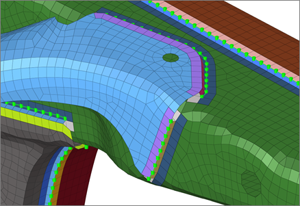
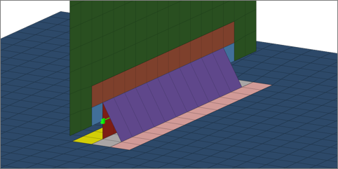
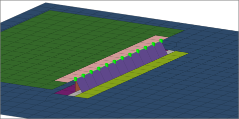
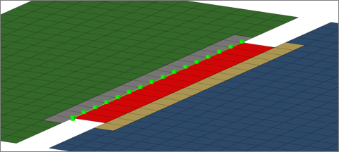
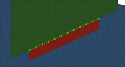
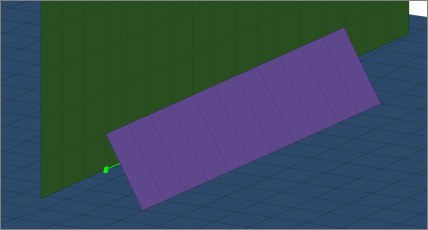

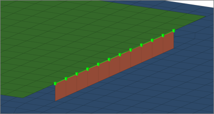
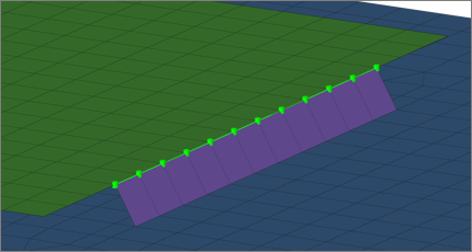
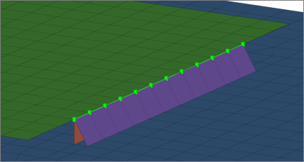
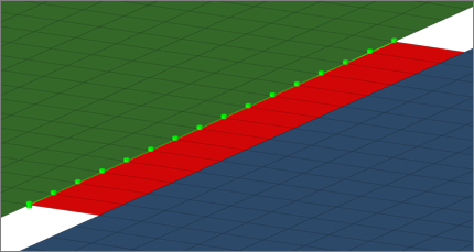
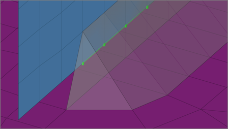
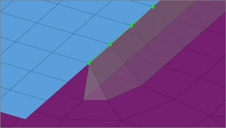
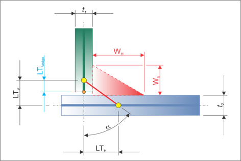
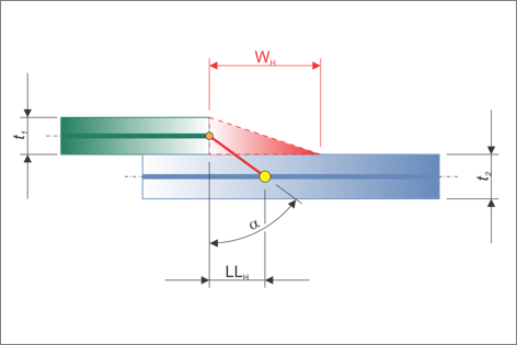
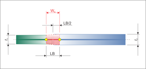
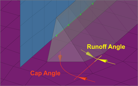
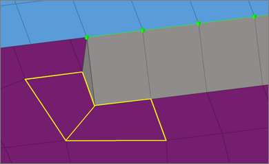
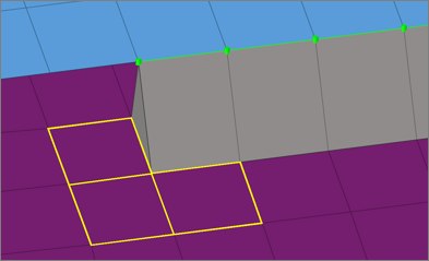
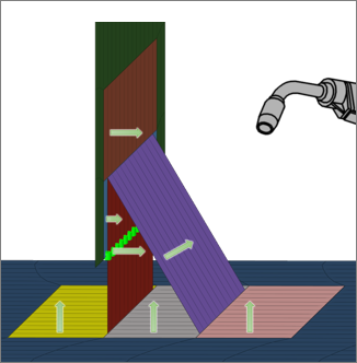
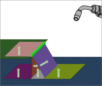
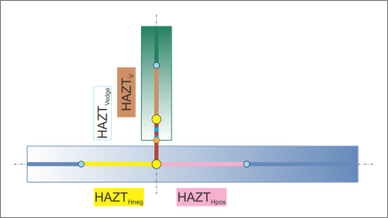
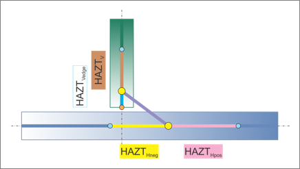
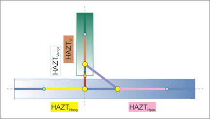
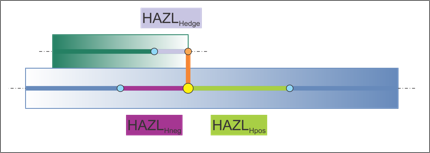
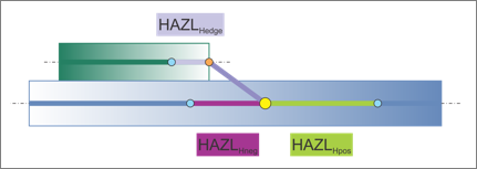
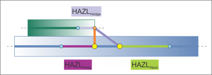
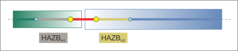
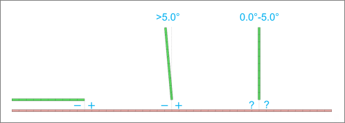
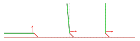
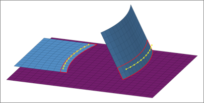
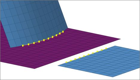
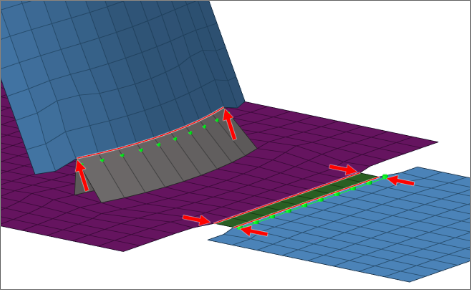
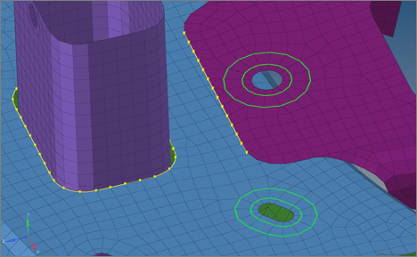

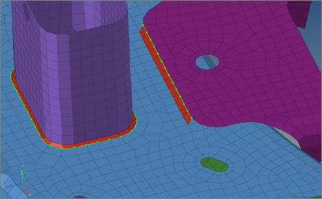
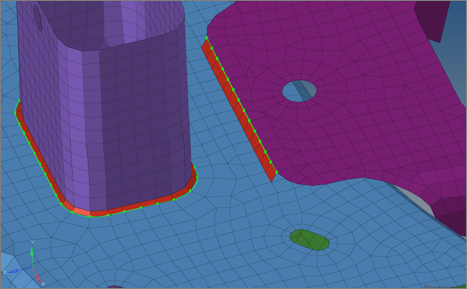
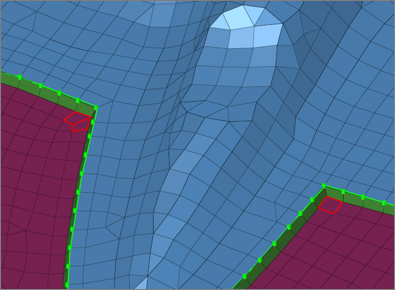

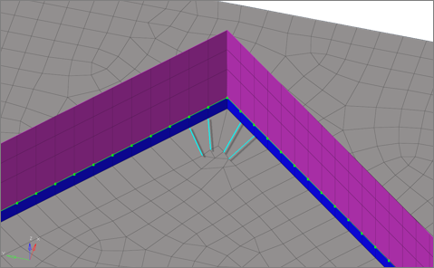
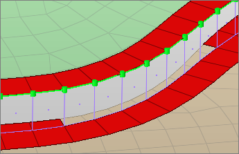
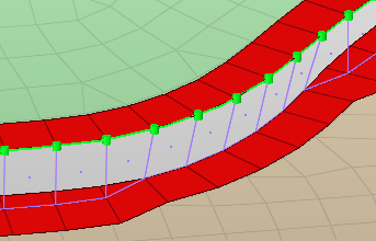
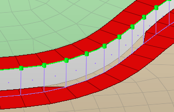
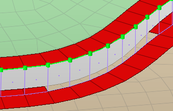
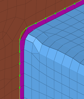 Figure 50. Without Seam Consider Feature and Boundary
 Figure 51. With Seam Consider Feature and Boundary