Attachments and Connectors
Attachments are an entity to facilitate the ease of joining subsystems.
Attachments are a single linked entity that own the realization to the Part. They can be referred to as links by a select subset of connectors. This list of attachments compatible connectors will grow over time to encapsulate more workflows. The workflow for creating these connectors between attachments can be done automatically through a proximity search basis. You can also convert existing connectors or absorb existing elements into a connector or attachment.
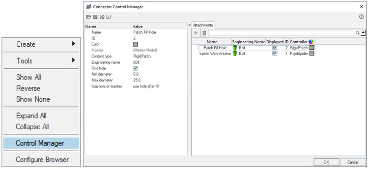
Figure 1.
Support Attachment and Subsystem Connector Realizations
There are two types of supported attachments: RigidSpider and RigidPatch. The RigidSpider creates a rigid element or series of rigid elements within the feature with a central node as the interface. The RigidPatch creates elements inside the hole, or as a layer of elements around the hole. These elements are then created with RigidBodies or Mat Rigid cards depending on the solver.
There are a select few supported subsystem connectors that link the attachments together. There is the RigidPatch for RigidPatch attachments, and the bolt (general)/bolt (cbar) for the RigidSpider attachments. The RigidPatch subsystem connector is used with Constrained Rigid Bodies for LS-DYNA, and Rigidbodies for OptiStruct.
The bolt (general) creates a single rigid element from the center node of one attachment realization to another. The bold (cbar) creates a bar/beam element from the same attachment realizations.