Find Evaluation Positions
The main objective of this function is to find the evaluation locations or positions for each of the 1D weld elements. The evaluation positions vary for each weld type.
Evaldist value is used
to find the evaluation positions.The following inputs are required to determine the evaluation positions:
- Evaluation distance
- Weld width factor
- Shell thickness
- Direction vectors for the 1D elements
The calculations to arrive at the evaluations positions for the different types of welds are shown below.
For T and L Welds
- Evaluation Distance
Evaldist = Standard distance from the specification- Weld Width
Weldwidth = Weld Width Factor * Min Shell Thickness- Evaluation Position from Weld Element Centroid
(Thickness / 2.0) + Evaldist + Weldwidth
For B and O Welds
- Evaluation Distance
Evaldist = Standard distance from the specification- Weld Width
Weldwidth = Weld Width Factor * Min Shell Thickness- Evaluation Position from Weld Element Centroid
Evaldist + Weldwidth
Using this relative evaluation distance and the centroid data of the 1D element, the absolute coordinates of the evaluation positions are determined.
For each of these evaluation positions, the nearest shell element and the closest node of the shell element are determined. These entities will be used to get the stress results.
Evaluation Distance with 1 Point
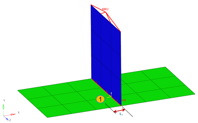
Figure 1.
Auto evaluation distance calculation
Example: T weld
Method: Auto
L1 = (Shell Thickness / 2.0) + Evaldist 1 + Weldwidth
where,
- Evaldist1
1.5 * Min Shell Thickness- Weld Width
Weld Width Factor * Min Shell Thickness- Stress
- Stress is queried from Element at L1
- For Manual Distance, L1 is directly specified by the user.
- HyperLife supports evaluation distance with 1 Point for DVS1612 and EuroCode 3.
Evaluation Distance with 2 Points
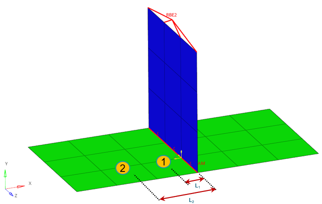
Figure 2.
Auto evaluation distance calculation
Example: T weld
Method: Auto
L1 = (Shell Thickness / 2.0) + Evaldist 1 + Weldwidth
L2 = (Shell Thickness / 2.0) + Evaldist 2 + Weldwidth
where,
- Evaldist 1
0.5 * Min Shell Thickness- Evaldist 2
1.5 * Min Shell Thickness- Weld Width
Weld Width Factor * Min Shell Thickness- Extrapolated Stress
1.5 (Stress at L1) - 0.5 (Stress at L2)- Stress at L1
- Stress is queried from Element at L1
- Stress at L2
- Stress is queried from Element at L2
- For Manual Distance, L1 and L2 is directly specified by the user.
- When evaluating with element data, the stress is taken from the closest element centroid. This is not necessarily matching the exact evaluation distance.
- HyperLife supports evaluation distance with 2 Points for FKM.
Evaluation Distance with Corner Data
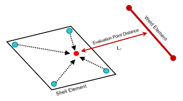
Figure 3.