1D and Shell Element Connections
HyperLife Weld Certification creates 1D beam elements at the intersection of the shell components. These elements are considered to be representations of the weld elements.
These welds are classified into six different categories based on the shell element arrangement at the intersections.
- T-Welds
- L-Welds
- Butt Welds
- Overlap Welds
- Cross (X) Welds
- Multiple (M) Welds
| Weld Type | Illustration |
|---|---|
| T - Welds | 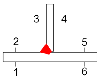 |
| L - Welds | 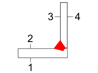 |
| Butt Welds | 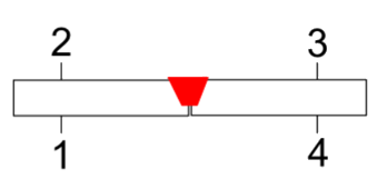 |
| Overlap Welds | 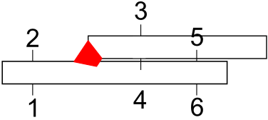
|
| Cross (X) Welds | 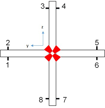 |
| Multiple (M) Welds | 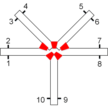 |
The weld elements are organized into different components.
Each of the 1D elements have a coordinate system that represents the weld coordinate
system.
- The X-axis is along the weld line.
- The Y-axis is normal to the X-axis and points towards evaluation position 1.
The coordinate systems are stored as part of the 1D element definition. A beam element always has a direction. For visualization, HL-WC also displays a coordinate system for each weld line. The purpose of these coordinate systems are for illustration only and not for evaluation.