Models that can be stored in the databases are:
| • | the active model (the model already displayed on the screen) |
| • | a model coming from the database (click Model from DataBase) |
To learn how to search for a model in the databases, see Search.
| 1. | From the Menu Bar, select Process > Model Manager > Maintenance. |
| 2. | Activate the Store/Modify tab. |
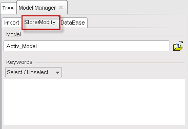
| 3. | Select a model to store in a database (active model or another model from a database). |
| 4. | Set some keywords by clicking Select / Unselect. |
| • | Select: the selected keywords are displayed in the keyword drop-down list in red and are also displayed in the window, Keywords. Choose a word from the drop-down list to be added to the window. |
| • | Unselect: choose an already selected keyword (in red) from the drop-down list to remove it from the Keywords window. |
The list of available databases appear in the window DataBase Tables.
| 4. | Click the desired database to select it. |
| 5. | If necessary, change the directory where the model will be written. |
| 6. | If necessary, add comments in the window, Comment. |
This text will be displayed in the HyperCrash Message window when the model is loaded.
After the previous steps are completed, the new submodel can be stored in the selected database.
| 8. | Click Add to DataBase to store the model. |
The models in the databases are saved in RADIOSS Block Format under the name, NAMEB00.
Any parameters can be modified and the submodel can be saved one more time as a new one (click Add to DataBase) or as a modified model (click Save modified).
Neighborhood
The neighborhood of the model can be defined by clicking Neighborhood.
This function creates a volume defined within a box. When the model, stored in a database is loaded and contains neighborhood information, HyperCrash is able to find the parts which are in this box.
| 1. | Click  and pick a node in the graphic window (center of the box). and pick a node in the graphic window (center of the box). |
or
Click  and pick point on shell in the graphic window
or
Enter the coordinates X, Y, and Z of a point (center of the box).
| 2. | Click  to view the coordinates of the node or the point. to view the coordinates of the node or the point. |
| 3. | Set the cube length in the field next to Cube length. |
| 4. | Click Ok to save and then Close; or |
| 5. | Click Cancel to cancel and then Close. |
Move model
| 1. | The model can be moved (translations, rotations, symmetry, etc.) by clicking Move model. |
To learn how to move a model from the database, see move with defined displacement.
| 2. | Click Ok to save and Close; or |
| 3. | Click Cancel to cancel and Close. |
Connection Marks
The connection marks can be used to predefine some connections on the model stored in the database. Those connections will be used later on to link the model in the database to the main model.
Create Spot Marks
To learn the details about the spotweld modeling, please see Connections / Spotweld.
| 1. | Click  and pick a part in the graphic window. and pick a part in the graphic window. |
or
Click  to include parts from the tree selection.
| 2. | Set a location with the Element or Node menus. |
With Element:
| • | Click  and select an element in the graphic window; or. and select an element in the graphic window; or. |
| • | Set a Shell Element Id and click Ok. |
With Node:
| • | Click and select a node in the graphic window; or |
| • | Click and select a point on the spotweld in the graphic window; or |
| • | Set a Node Id and click Ok, or |
| • | Set point coordinates X, Y, and Z and click to view. |
After setting the location
| 1. | Set the Name of the spot mark. |
| 2. | If necessary, set a Comment for this spot mark. |
The comment will be displayed in the HyperCrash Message window.
| 3. | Click Save as new to save this spot mark. |
Create Bolt Marks
To learn the details about the bolt modeling, please see Connections / Bolt.
| 1. | Click and pick a part in the graphic window. |
or
Click to include parts from the tree selection.
| 2. | Set a location with the Element or Node. |
With Element:
| • | Click and select an element in the graphic window, or |
| • | Set a Shell Element Id and click Ok. |
With Node:
| • | Click and select a node in the graphic window, or |
| • | Click and select a point on the shell element in the graphic window; or |
| • | Set a Node Id and click Ok, or |
| • | Set point coordinates X, Y, and Z and click to view. |
| 3. | After the Location is set, click the Direction tab for modification, if necessary. |
The default orientation is determined by the normal of the selected element or the average normal of the elements linked to the selected node.
To redefine the bolt direction
| 1. | Deselect the button Normal to element(s). |
| 2. | Define a Direction with the vector coordinates X, Y, and Z. |
or
Click  and pick two nodes in the graphic window to define a vector.
Set the Properties of the bolt
| 2. | If necessary, enter a Comment for this bolt. |
This comment will be displayed in the HyperCrash Message window.
| 4. | Select the type of bolt: Bolt with spring or Rigid Bolt. |
| 5. | In the case of "Bolt with spring" type, select the property for the spring. |
| 6. | Click Save as new to save this bolt mark. |
View a spot mark or a bolt mark
| 1. | Select a spot mark or a bolt mark in the list window. |
| 2. | Click  to view it. to view it. |
| 3. | All the parameters of the spot marks or bolt marks can be modified. |
| 4. | Click Save modified to save the modified spot mark or bolt mark; or |
Click Save as new to create a new spot mark or a new bolt mark.
Delete a spot mark or a bolt mark
| 1. | Select a spot mark or a bolt mark in the list window. |
| 2. | Click  to delete it. to delete it. |
| 3. | Answer the question at the bottom right of the screen with Yes or No. |
| 4. | After creating all the needed spot marks and bolt marks, return to the main menu by clicking Back to Store / Modify. |


