Define/Edit Pane
The Define/Edit Pane, the central pane of the HyperLaminate window, allows you to edit the definition of the selected entity.
On selecting an entity in the Laminate Browser the Define/Edit pane is populated with the current definition. The configuration of the Define/Edit pane differs for different user profiles and sub-types (card images).
Materials
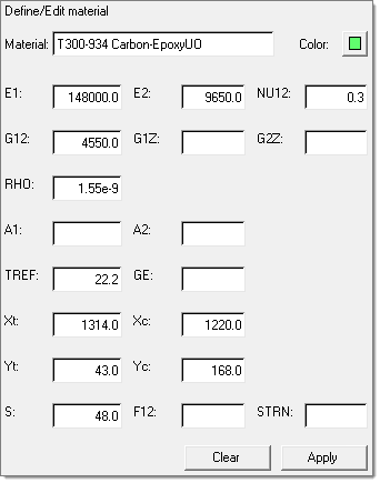 Figure 1. OptiStruct Materials – MAT8 |
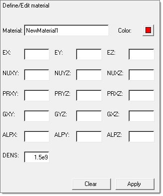 Figure 2. ANSYS Materials – MATERIAL |
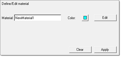
Figure 3. Abaqus Materials – ABAQUS_MATERIAL
Laminates
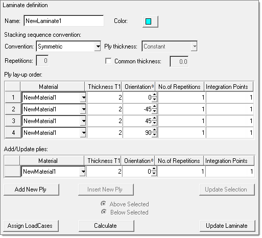
Figure 4. Abaqus Laminates – SOLIDSECTION
- Total
- The Ply lay-up order table describes the laminate in its entirety.
- Symmetric
- The Ply lay-up order table describes the bottom half of the laminate. The top half of the laminate is the mirror image of the bottom half. The ply angles used for the top half are the same as the ply angles used in the bottom half.
- Antisymmetric
- The Ply lay-up order table describes the bottom half of the laminate. The top half of the laminate is the mirror image of the bottom half. The ply angles used for the top half have the opposite sign to the ply angles used in the bottom half (but 0, 90, 180, 270, and 360 remain as 0, 90, 180, 270, and 360, respectively).
- Symmetric-Midlayer
- The Ply lay-up order table describes the bottom half of the laminate and a midlayer (or core). The midlayer is the last ply defined in the table. The top half of the laminate is the mirror image of the bottom half. The midlayer is not reflected. The ply angles used for the top half are the same as the ply angles used in the bottom half. Due to the midlayer, the total number of plies is always odd.
- Antisymmetric-Midlayer
- The Ply lay-up order table describes the bottom half of the laminate and a midlayer (or core). The midlayer is the last ply defined in the table. The top half of the laminate is the mirror image of the bottom half. The midlayer is not reflected. The ply angles used for the top half have the opposite sign to the ply angles used in the bottom half (but 0, 90, 180, 270, and 360 remain as 0, 90, 180, 270, and 360, respectively). Due to the midlayer, the total number of plies is always odd.
- Repeat
- The Ply lay-up order table describes a single sub-laminate which is repeated a number of times. The number of repetitions is determined by the number entered in the Repetitions: field (which is activated when this Convention is chosen).
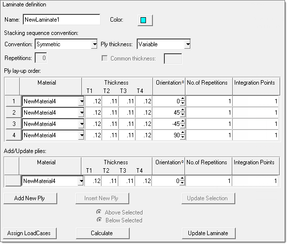 Figure 5. ANSYS Laminates – SHELL99
It is also possible to choose a common thickness for all plies. Common thickness gives every ply in the laminate the same thickness.
The Ply lay-up order table describes the laminate from the bottom ply (most negative Z) moving upwards (increasing in positive Z direction). Each row of the table defines the material, ply thickness and ply orientation for a number of plies (defined by the No. of repetitions field and based on the selected Convention). The number of integration points for each ply (or group of plies) is also provided in the table. This number is used by the HyperLaminate Solver, as well as the external FEA solver when applicable.
Rows are added to the table by completing the Add/Update plies: entry fields and clicking Add New Ply. Rows may be inserted in the table, either above or below selected rows (choose from the Above Selected or Below Selected radio buttons), by clicking the Insert New Ply button. Rows may be cut, copied from, pasted to, or deleted from the table using the Toolbar, pull-down Edit menu, or Ctrl+X, Ctrl+C, Ctrl+V, and Ctrl+D respectively. Select multiple rows by selecting one row and then, with the Ctrl key held down, selecting other rows (alternatively, multiple rows may be selected with the Shift key held down; this will retain the current selection and add all the rows between the current selection and the newly selected row). Rows are always pasted above the selected rows when multiple rows are selected the clipboard contents are pasted above each selected row.
All fields in the Ply lay-up order table may be edited. It is also possible to edit multiple rows at once. Select multiple rows as described in the previous paragraph. When multiple rows are selected, the Add/Update plies: fields are populated with the information common to the selected rows. Blank fields indicate that not all of the selected rows contain the same values for that field. Changes can be made to the Add/Update plies: fields and Update Selection can be clicked to update the selected rows with the updated information (no changes occur to the selected rows for blank fields).
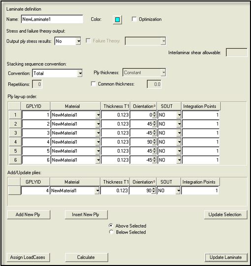
Figure 6. OptiStruct Laminates – PCOMPG
The Ply lay-up order table for the OptiStruct and Nastran PCOMPG laminate sub-type is different from other laminate sub-types in that it has a GPLYID field. This field is used to assign a global ply ID to a ply definition (the global ply ID is a post-processing aid). As this ID should not be repeated within the same laminate, the No. of repetitions field is not available for PCOMPG. For PCOMPG each row in the Ply lay-up order table should represent a single ply so only the Total stacking convention should be used for PCOMPG, but this is not enforced in the GUI.
For the OptiStruct and Nastran user profiles it is possible to assign a design variable to a thickness or orientation field in the Ply lay-up order table. Checking the Optimization checkbox expands the Ply lay-up order table, adding extra fields to the right of the Thickness T1 and Orientation 0 fields. Design variables may be selected in these extra fields. Selecting a design variable to the right of a thickness or orientation assigns the selected design variable to that thickness or orientation.
Click Update Laminate to apply all the changes for the current HyperLaminate session (it is important to remember that the HyperMesh database is only updated on exit from HyperLaminate).
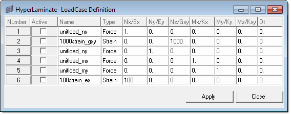
Figure 7. LoadCase Definition GUI
HLS loadcases with a check in the Active column are selected for the current laminate. Different HLS loadcases may be selected for different laminates. Having selected the appropriate loadcases, click Apply and then Close to exit the dialog.
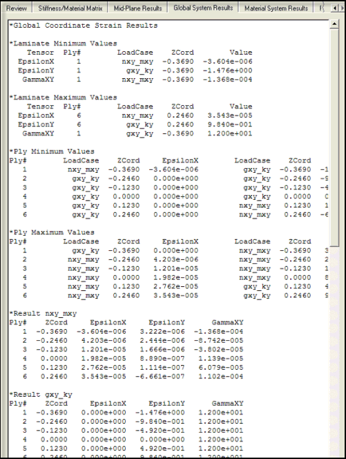
Figure 8. Hyperlaminate Solver results
HLS Loadcases
For all user profiles the HLS loadcases branch allows various in-plane loading scenarios to be defined and stored. The loading scenarios can be either load based or strain based. All information for the selected HLS loadcase may be edited in the Define/Edit pane. Once the desired changes have been made, clicking Apply will save those changes for the current HyperLaminate session. It is important to remember that the HyperMesh database is only updated on exit from HyperLaminate. To reset all fields for the selected HLS loadcase to zero, you can click Clear.
Design Variables
For the OptiStruct and Nastran user profiles, the DESVAR design variable card is supported in HyperLaminate. All information for the selected design variable may be edited in the Define/Edit pane. Once the desired changes have been made, clicking Apply will save those changes for the current HyperLaminate session. It is important to remember that the HyperMesh database is only updated on exit from HyperLaminate. To reset all fields for the selected design variable to their default values, you can click Clear.