Ray Data
ProMan offers the possibility to write the data corresponding to the calculated propagation paths into an ASCII (.str) or a binary (.ray) file. This optional output (ASCII version) is required for the evaluation of the radio channel characteristics and can be selected by clicking and click the Propagation tab. Besides this, the ray data contained in these files can be used to do further post-processing with other tools, for example, calculation of angles of arrival / departure, angular spreads.
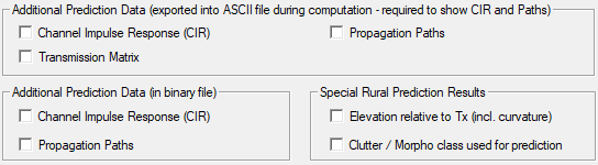
Figure 1. The Additional Prediction Data dialog.
There are different output alternatives within this ray data file, depending on the selected propagation model, the computation mode, the environment under investigation and the enabled outputs on the Propagation tab.
The output of the transmission matrix and the corresponding vector of the electrical field strength is only available, if the standard ray-tracing model (based on indoor databases) is selected in combination with the Fresnel (reflection, transmission) and GTD / UTD (diffraction) model for the calculation of the rays in indoor scenarios. The transmission matrix is always optional, whereas the channel impulse data is always written (if the output of propagation paths is selected).
The ASCII ray file written by ProMan contains a header
section with general information about the evaluated scenario, such as lower-left corner,
resolution of the prediction area and the specified parameters of the transmitter. After
the header section the data section with the ray information for each predicted pixel
starts. Coordinates of predicted pixels are indicated with the keyword
POINT. Subsequent the ray data belonging to this pixel follows
indicated with the keyword PATH for each available propagation path.
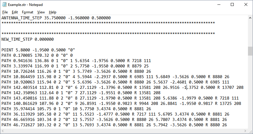
Figure 2. Result file with detailed ray information in ASCII format.
Urban or Indoor Propagation Scenario

Figure 3. Channel impulse response.
Figure 4. Channel impulse response with transmission matrix.
Figure 5. Path data with transmission matrix.

Figure 6. Data contained in an ASCII ray file.