Antennas are mounted on arms. They are orthogonal to the surface (mast or wall) and always
consist of a pair of two arms, one above the other. At these arms, a tube is mounted
vertically. At the tube, there are at least two sub-arms to mount the antennas on the
tube.
All elements of the arms and sub-arms are geometrically centered. The cross-section of the
tubes is always circular. The tube is open at its ends, see Figure 1.
Sometimes the antenna is mounted at the tube without sub-arms, see Figure 2. Therefore, you can
enable or disable the sub-arms for each antenna individually in MASC.
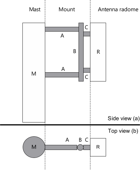
Figure 1. Side-view (a) and top view (b) of the arms (A) mounted at the mast (M). The
antenna (R) is mounted with sub-arms (C) at the vertically oriented tube (B).
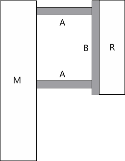
Figure 2. Side-view of the arms (A) mounted at the mast (M). The antenna (R) is mounted
without sub-arms at the vertically oriented tube (B).
For each arm, the azimuth can be defined individually. North means 0° with increasing
values towards East (90° means East). So multiple arms and antennas can be arranged around
a single mast.
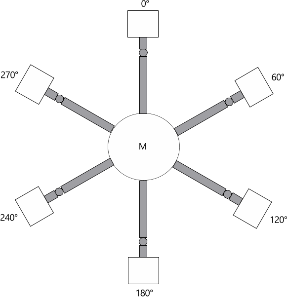
Figure 3. Top view on a configuration with six arms with different azimuth angles
Antennas can be rotated in azimuth relative to the arm, see Figure 4. The rotation axis is the
vertically mounted tube, and the sub-arms are also rotated together with the antenna. As
this azimuth value is relative to the orientation of the arm, an azimuth of 0° is equal to
the direction of the arm. Positive values for the azimuth are describing a rotation
clock-wise (from top-view).
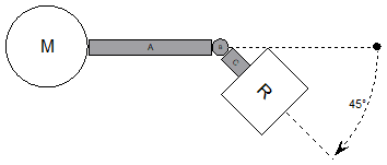
Figure 4. Top view of a 45° azimuth rotated antenna. Antenna (R) and sub-arm (C) are
rotated in the horizontal plane around the tube (B). The location of the arms (A) and
tube (B) is not influenced.
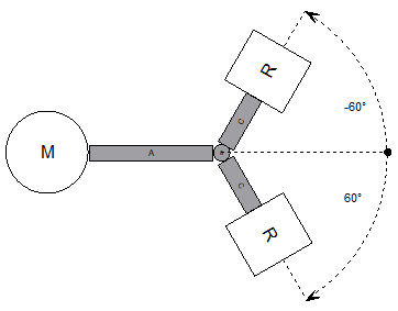
It is also possible to mount multiple antennas with different azimuth at one tube/arm. The
number of antennas to be mounted on the same arm is not limited by MASC.
Figure 5. Top view on a configuration with two antennas (R), mounted at one tube/arm. The
azimuth of the antennas is ±60°.