Powertrain Modeling
Overview
The steps for Powertrain modeling are as follows:
- Import CAD
- Create component sets
- Defeature CAD as necessary (Optional)
- Facet powertrain assembly
- Patch openings and review
- HX Modeling
- Wrap with wrap controls (Assembly by assembly or entire underhood)
- Wrapping quality: Check for bridging and that features are captured
- Decimate (may not want to decimate too much)
Process
- Import associated CAD for the powertrain:
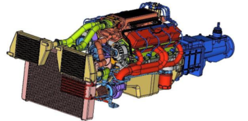
Figure 1. - Create sets based on analysis:
- Tools pull down > Create sets of components
- Model browser > Show/Hide components by sets for further steps
- Use sets to select component -> by sets
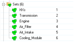
Figure 2.
- Defeature Geometry (Optional):
- Simplify model to avoid modeling unnecessary features like logos, solid holes, fillets, and so on
- Find small parts and delete them
- Use find_smallParts.tcl script
- Define 10 as threshold to find small parts (Generally nuts and bolts)
- It will create a set will small parts based on tolerance
- Right click Isolate only to review the parts
- F2 to open delete panel Select parts to delete
- Remove logo (Geometry --> Auto cleanup)
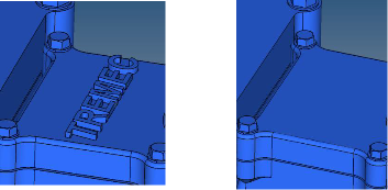
Figure 3.- Select logo and surrounding surface
- Selection does not need to be precise
- It should cover all logo surfaces and surrounding surfaces
- You can select all surfaces as well
- Measure logo height beforehand to define in this utility
- Simplify parts
- Select logo and surrounding surface
- Solid hole removal
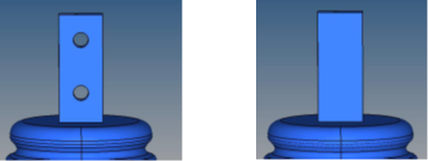
Figure 4.- Use solid hole removal in Geometry ribbon
- In edit parameters, turn on the option to remove solid hole
- Define max radius as 20 (Choose radius according to selection)
- Create primitive shapes to model complex parts with cylinder, sphere or block
- Tessellate CAD:
- Once done with geometry editing tool, tessellate the CAD to further
work on mesh-based tools like wrapper, hole gap patch, and so on
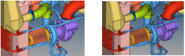
Figure 5. - Use rigid body mesher to tessellate
- Define following parameters (for model in mm scale)
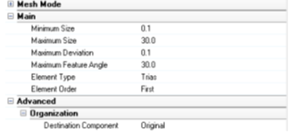
Figure 6. - Tips:
- Change Max and min sizes according to scale of the model and level of details required.
- Review tessellated mesh
- Review that tessellation captures original shape as required
- Review free edges:
- Tools > Edges > Free edges
- Delete geometry to make model lighter (Surfaces and Solids)
- Once done with geometry editing tool, tessellate the CAD to further
work on mesh-based tools like wrapper, hole gap patch, and so on
- Patch:
- Patch complex areas, gaps, solid opening
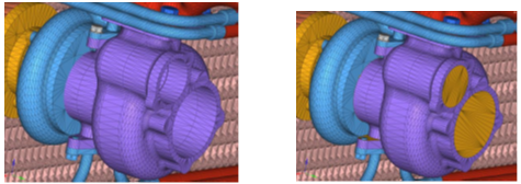
Figure 7. - Patch openings, solid holes (Mesh pull down --> Hole/Gap fill àHole
fill): Here you need to close opening of pipes, solid holes so the
wrapper does not go inside parts; if this happens, you get exterior
surfaces as wrap results
- Switch to Fill mode to “Hole fill”
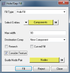
Figure 8. - Select all components
- Turn on Consider features which will consider solid holes as well.
- Define hole width: 100
- Measure the hole length you want to close and define it as max width
- For powertrain and underhood cases start with max width as 50
- Review patches. Delete patch elements if not required
- Manual patch as required by selecting Faces or edges instead of components
- Switch to Fill mode to “Hole fill”
- Close gaps in the model
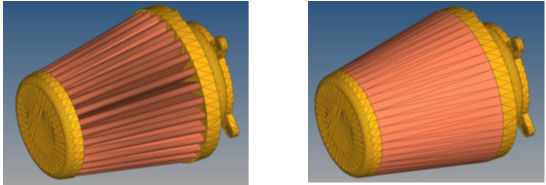
Figure 9.- Switch to Fill mode to “Gap fill”
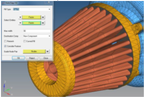
Figure 10. - Select opposite faces one in each group
- Turn on Consider features.
- Measure the gap length you want to close and define it as max width
- Switch to Fill mode to “Gap fill”
- Cover slots so that they are not exposed to wrapper; they are not
useful for analysis
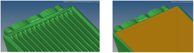
Figure 11.- Switch to Fill mode to “Patch fill”
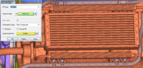
Figure 12. - Select Nodelist
- Select nodes which covers shape. For a flat area, 4 nodes should be enough
- Switch to Fill mode to “Patch fill”
- Patch complex areas, gaps, solid opening
- Model Heat exchanger (HXs):
- When you are given detailed HXs with fins and tubes, model them
using boxes
- Create HXs boxes
- Delete the fins and tubes
- Only retain HX shroud
- Do not include HX box components in wrapping
- After wrapping, connect HX box and wrapped parts (required
for AcuSolve only)
- Mesh pull down > Boolean
- Select all wrapped components and HX boxes
- Define Boxes as master > Boolean
- Create HX boxes
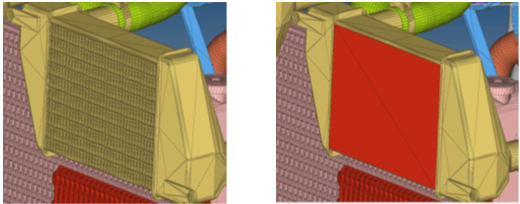
Figure 13.- Mesh pull down > Hole/Gap Fill
- Switch to Fill mode to “Patch fill”
- Switch selection to Nodelist
- Select four corner nodes which covers fins and tubes
- Do it for both inlet and outlet
- Create a side walls using same tool
- Organize elements in appropriate components
- Use Tools panel > Translate to enclose HX in corresponding
box
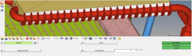
Figure 14.
- When you are given detailed HXs with fins and tubes, model them
using boxes
- Wrap setting - Mesh Controls:
- Define wrapper settings
- Mesh pull down > Mesh controls
- Right click > Adaptive wrap folder > Create > Model
- Select wrapper type: external wrapper
- External wrapper for external flow analysis e.g. underhood thermal
- Cavity wrapper for internal flow analysis e.g. thermal comfort.
- Select volume definition: All
- Available options (All/Nth largest/Enclosed by node/Exclude by node) – See the help for more details
- Select components to be wrapped
- Define wrapping parameters:
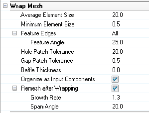
Figure 15.
- Tips:
- Min size should be based on the smallest feature length to be captured. (Rule of thumb – min size = 1/3rd of smallest thickness)
- If all gaps are patched using “Hole/gap fill” tool, define
gap patch tolerance as min size.
- Defining bigger gap patch tolerance can create bad wrap mesh
- Define local controls if any other wrapping size is required locally
- Define Proximity Controls to avoid contacts between selected
parts
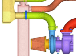
Figure 16.- Define proximity controls
- Select all HX, Air filter and neighboring shroud components
- Define search floor. Any thing less than value will be
refined
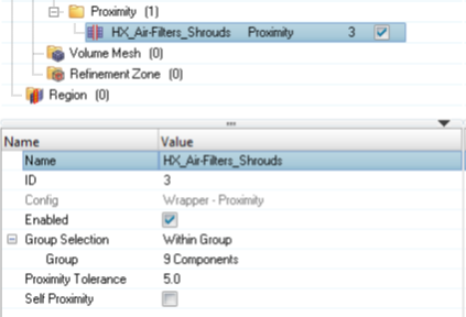
Figure 17. - Leak Detection to verify if any leaks present in the model
with given selection and parameters
- Define a source node inside the wrapping domain
- Make sure source node is enclosed properly and not close by any elements
- Define multiple target nodes outside the volumes.
- Define many target nodes and distribute them at different location
- This way you have a greater chance of finding
all possible leaks at once
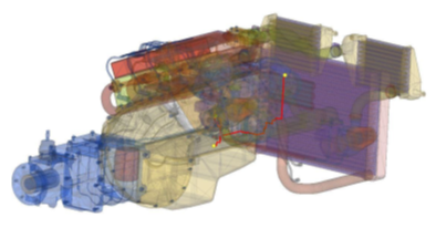
Figure 18.
- Run wrapping:
- Right click on adaptive wrap folder -> Mesh
- If leak detection mesh control is defined and there is a leak, it will terminate wrapping with leak path.
- Define a source node inside the wrapping domain
- Define wrapper settings
- Review wrap results:
- Review wrap results and validate it before tetmeshing. After
wrapping, there will be a new assembly creates which will contain
wrapped results
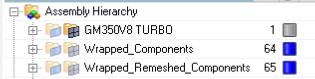
Figure 19. - Check intersections:
- 3d panel > Tetramesh > Select all wrapped components > Check 2d mesh
- Define intersection tolerance (for mm scale 0.001 and di-hedral angle as 5)
- Wrapped results mostly will not have any intersection.
- But sometimes you can see few intersections which can be resolved using 2d panel > Replace
- Check free edges and t-connection
- Tools panel > Edges > Select all wrapped components > Free edge/t-connection
- Wrapped results should not have any free edges/t-connections
- Analyze volume wrapper has created
- Use volume_analyser.tcl script
- Only display wrapped components (either wrapped or remeshed)
- It will create a sets with possible volumes and you can review each volume as well
- Review wrap results and validate it before tetmeshing. After
wrapping, there will be a new assembly creates which will contain
wrapped results
- Decimation:
- If solver is uFx/PowerFlow, it is required to have minimum element count for post processing purpose
- Decimation reduces elements count retaining sharp features intact
with minimal geometry deviation
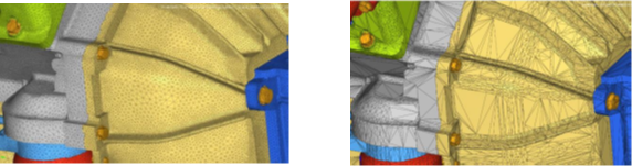
Figure 20.- Use Decimation scripts to coarsen mesh
- Select components to decimate
- Define decimation factor: 0
- 0: Provides least deviation from input
- 1: Enables maximum possible deviation
- Define feature angle: 30
- Use Decimation scripts to coarsen mesh