Build Block Diagram
Build the Block Diagram presenting the process in the form of a flow chart.
-
From the Application Mapping dialog, select the
application CADFeko 2021.1.
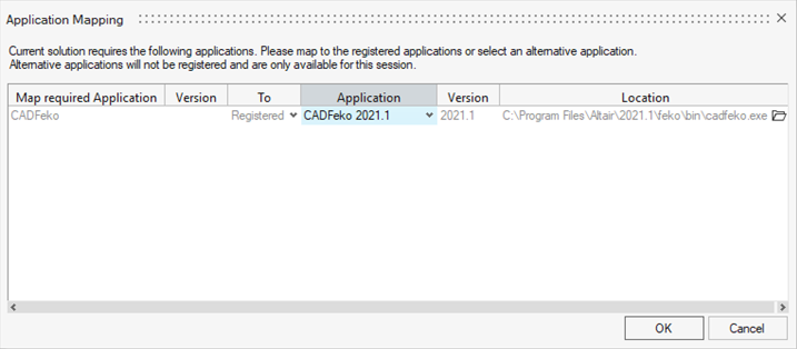
Figure 1. -
In the Block Diagram, connect the Solution - High Frequency EM1 outputs to the
Powerloss to Heat inputs.
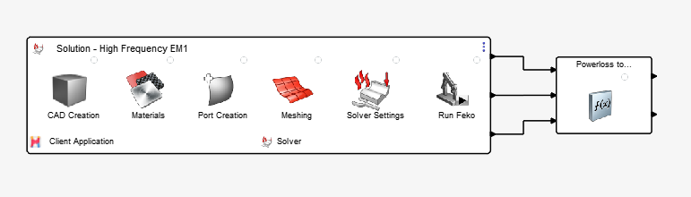
Figure 2. -
In the Block Diagram, connect the Powerloss to Heat outputs to the Solution -
Thermo-Mechanical2 inputs.
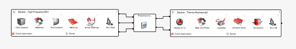
Figure 3. -
Launch Task.
-
From the Author ribbon, Create group, click the Launch
Task tool.

Figure 4.The Entity Editor opens. -
Click in the Application field, and select
 from the drop-down menu.
-
In the Advanced Selection dialog, select
HyperWorks HV as the Application and click
OK.
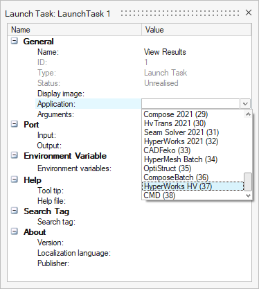
Figure 5. -
In the Entity Editor, enter -f
$ALTAIR_PULSE_WORKDIR/MyOSStep5.h3d for the Argument and
click Close.
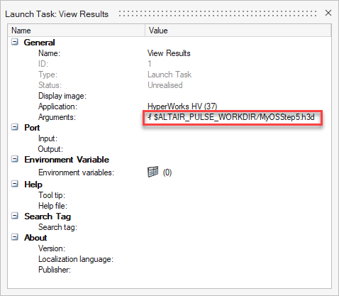
Figure 6.
-
From the Author ribbon, Create group, click the Launch
Task tool.
-
In the Block Diagram, right-click the Output port for View Results and select
Delete from the context menu.
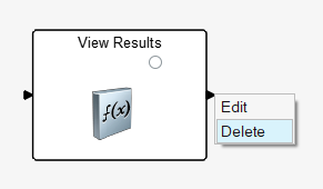
Figure 7. -
Connect the Thermo-Mechanical2 output to the View Results input.
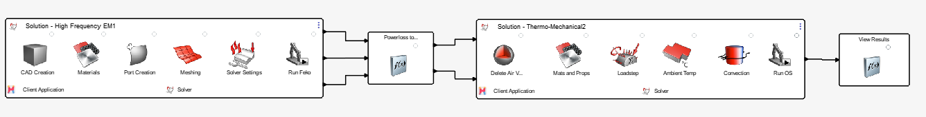
Figure 8. -
From the Author ribbon, Execute Process group, click the
Run tool.

Figure 9.The simulation begins to run and the Entity Editor opens. -
In the Entity Editor, click
Close.
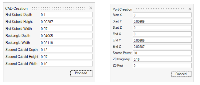 Figure 10.