View Control Points
This menu allows you to change the control points of surfaces. It is possible to view and edit the component values for each control point part of a surface. To use this menu, a surface has to be selected. Objects cannot be selected unless they are exploded and a single surface part of the object is selected.
To use this feature, select a surface, and then select View Control Points from the Edit menu or click the toolbar icon.
A new window will appear on the right side showing a table with all the x, y, z components for each control point the surface is made of.
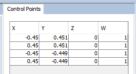
Figure 1. control point list
It is possible to select a row from this table in order to view the control point on the 3D viewer. For instance, click on a row to tint the control point to make it visible.
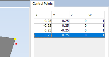
Figure 2. the control point is tinted yellow when the row is clicked.
Additionally, it is possible to click on a control point to select the row in the table.
If a control point gets selected, and then dragged using the mouse, it is possible to translate it, transforming the original geometry. This allows you to draw using the mouse the desired location of the control points. It is not possible to change the weight of such nodes using the mouse.
Alternatively, for a more precise behaviour, it is possible to double click a cell from the table and manually set the value for that cell. It is possible to change any cell, including position and weight for the control point.
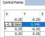
Figure 3. modifying the value for a component.
To exit this mode, simply select View Control Points again from the Edit menu or click the toolbar icon.