Run Analysis
Define parameters and execute an analysis to understand filling, packing, cooling or warpage events during molding. Generate results for individual or combined events.
Complete the model setup before running an analysis.
Note: Analysis results are saved
in the folder specified in your Preferences settings under Molding >
Analysis > Run Options.
-
Click Run Analysis on the Analyze icon..

-
Define the parameters for the analysis.
Tab Option Description Stages 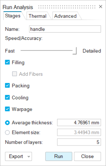
Name Type the name of the run. By default, the name of the model is used. Speed/Accuracy Adjust the slider to determine whether the results returned are faster or more detailed. - Drag the slider to Fast to apply an element size that is equal to the average thickness * 2.
- Drag the slider halfway between Fast and Detailed (Medium), to apply an element size that is equal to the average thickness * 1.2.
- Drag the slider to Detailed to apply an element size that is based on the thickness and number of mesh layers. The default number of layers = 5. The minimum number of layers for filling, cooling, and warpage = 2; packing = 4; fibers = 5.
Filling Select to examine the flow pattern, temperature and pressures associated with the material entering into the mold. Select the Add Fibers option to define the addition of fibers to the part material.Note: You must also define or select a material with fiber properties when assigning a material to your part during the analysis setup.Packing Select to calculate the pressure necessary during solidification to compensate for contraction due to temperature. Cooling Select to view cooling results in which solidification starts with a totally full mold and ends at a specified temperature or time. Warpage Select to examine evidence of warpage. Warpage can occur when a material shrinks non-uniformly due to high cooling rates, mold restraint, or temperature differences that create internal stresses. Note: You must also select the Cooling option to generate wapage results.Average thickness Enter the average thickness of the part. The software creates the mesh based on this value.
Element size Enter the average element size for the part cavity. The mesh is based on this value. Number of layers Enter the number of element layers to be generated. To reduce computation time, specify 3 to 5 layers. To improve accuracy, specify 6 or more layers. Thermal 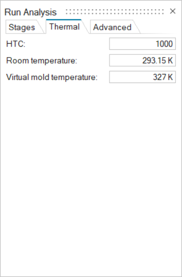
HTC Enter the Heat Transfer Coefficient. W/m2K Room temperature Enter the ambient temperature of the work environment Virtual mold temperature Set the desired starting temperature for the mold. Advanced 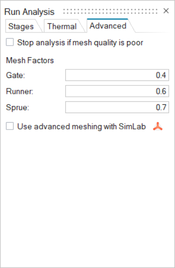
Stop analysis if mesh quality is poor If this option is selected, Inspire will run a quality check on the mesh settings. If the mesh quality is not high enough to yield accurate results, Inspire will stop the simulation. To mitigate this risk, review mesh size and mesh factors, or enable the Use advanced meshing with SimLab option. Mesh Factors Adjust the mesh size for each component: Gate, Runner, and Sprue. Enter a factor to multiply the Element Size by. The available range for each of the components is 0.1-5.
Use advanced meshing with SimLab If this option is selected, SimLab will be launched when you run an analysis so that you can perform advanced meshing. Note: SimLab must be installed for this feature to work. -
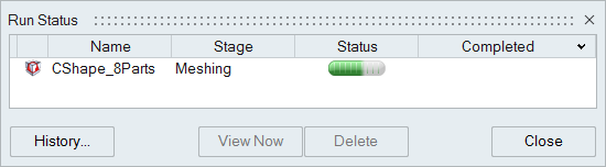
Click Run.
The run status is displayed.