Tutorial: Inertia Relief Analysis
Define a force using components and run an analysis with inertia relief.
- Apply forces and moments using component force mode
- Run an analysis with inertia relief
Overview
Inertia relief is a numerical method used for analyzing unconstrained structures. A typical example is an aircraft in steady flight where the lift, drag, and thrust loads are balanced by gravity acting on the mass of the total aircraft. This acceleration due to gravity is equal and opposite to the acceleration that would result for the unconstrained structure.
At a component level, with inertia relief it is possible to analyze a part in isolation if the loads at the interface points are known or can be measured/calculated and the part can be considered to be in static equilibrium.
- load setup
- running inertia relief
| Location | Shock | Pivot | Axle | |
|---|---|---|---|---|
| Force | Fx N | -2352 | 980 | 1372 |
| Fy N | 3211 | -3700 | 489 | |
| Fz N | -635 | 645 | 0 | |
| Moment | Mx N*mm | 0 | -104867 | -278 |
| My N*mm | 0 | -188238 | 779 | |
| Mz N*mm | 0 | 0 | -7998 |
Apply a Component Force to the Shock Mount
-
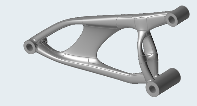
Double-click the 0.0_swingarm_IR_FEA.x_b file to load it
in the modeling window.
This is a solid model of a single part motorcycle swing arm.
-
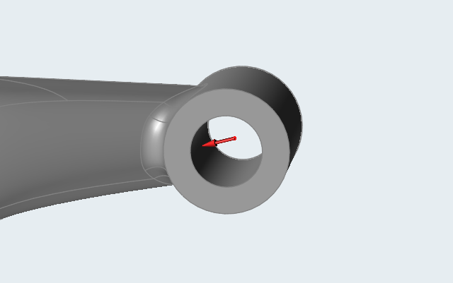
Select the Apply Force tool on the Structure
ribbon.

-
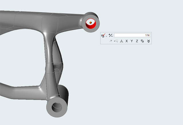
Click to apply the force to the hole center of the shock mount.
-
Switch to Component Force Mode on the microdialog, and
click the
 chevron
to expand it.
chevron
to expand it.
-
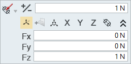
Enter the following values:
- Fx: -2352 N
- Fy: 3211 N
- Fz: -635 N
Apply a Component Force and Moment to the Swing Arm Pivot
-
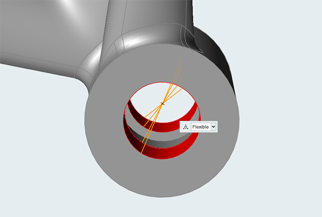
Select the Connectors tool.

-
Create a connector at the center of the hole by selecting the two faces as
shown:
-
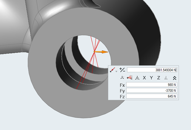
Select the Apply Force tool and apply a force to the
center point of the connector.
-
Switch to Component Force Mode on the microdialog, and
click the chevron to expand it.
-
Enter the following values:
- Fx: 980 N
- Fy: -3700 N
- Fz: 645 N
-
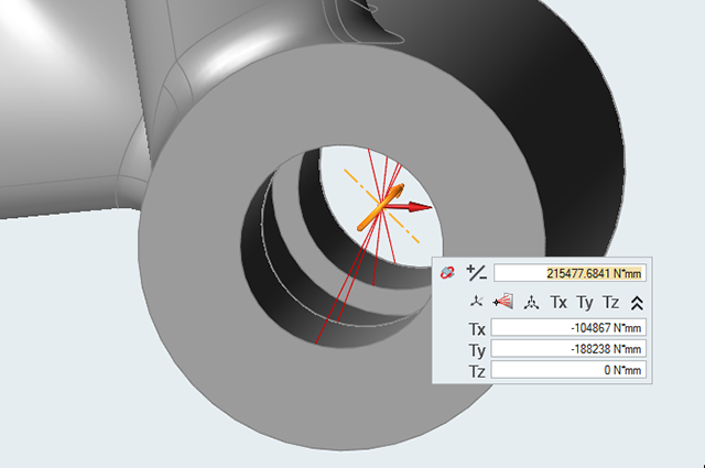
Select the Apply Torque tool and apply a torque to the
center point of the connector.

-
Switch to Component Torque Mode on the microdialog, and
click the chevron to expand it.
-
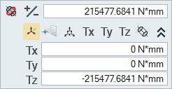
Enter the following values:
- Tx: -104867 N*mm
- Ty: -188238 N*mm
- Tz: 0 N*mm
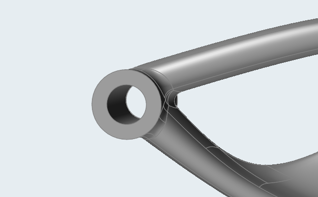
Apply a Component Force and Moment to the Center of the Axle
-
Zoom in on the center of the axle.
-
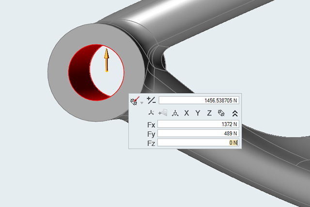
Select the Apply Force tool and apply a force to the
hole center of the axle.
-
Switch to Component Force Mode on the microdialog, and
click the chevron to expand it.
-
Enter the following values:
- Fx: 1372 N
- Fy: 489 N
- Fz: 0 N
-
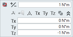
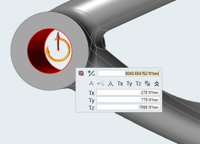
Select the Apply Torque tool and apply a torque to the
hole center of the axle.
-
Switch to Component Torque Mode on the microdialog, and
click the chevron to expand it.
-
Enter the following values:
- Tx: -278 N*mm
- Ty: 779 N*mm
- Tz: -7998 N*mm
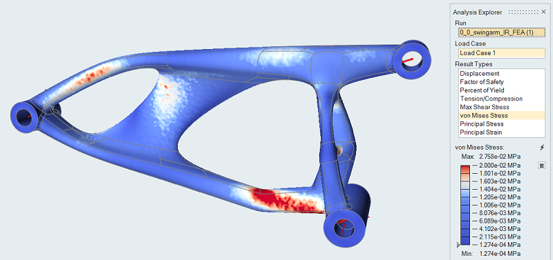
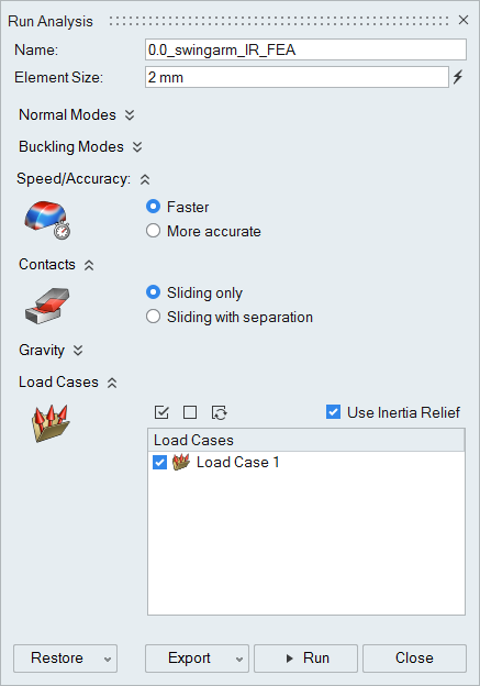
Run an Analysis with Inertia Relief
-
Click Run Analysis
 on the Analyze icon to open the Run Analysis
window.
on the Analyze icon to open the Run Analysis
window.

-
Use the following settings:
-
Change the Max value to 200
MPa.
Note: Even without supports, the analysis runs as any imbalance in the loads is reacted by the inertia forces.