Stamping
A stamping constraint should be used when the manufacturing process calls for stamping rather than casting.
A stamping constraint can be applied from the part context menu.
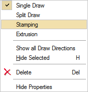
This type of constraint should be used when the manufacturing process calls for stamping rather than casting. When you run an optimization on a design space with a stamping constraint applied, the solver returns a result with uniform thickness while avoiding negative draft angles and internal voids.
When applying a stamping constraint, you may also specify the No Hole option in the microdialog to eliminate internal voids. Stamping constraints are valid for optimization but not analysis.
Apply a Stamping Constraint
Click on a design space and use the context menu to apply a stamping constraint.
- Click the
 icon on the microdialog to eliminate internal
voids in the optimized part.
icon on the microdialog to eliminate internal
voids in the optimized part.
Stamping Examples
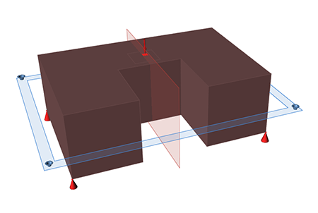
Figure 1. Design Space
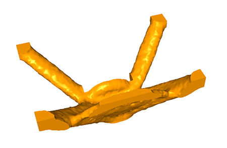
Figure 2. Optimized Shape with Stamping Applied
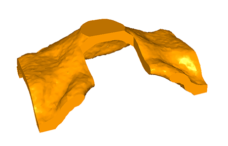
Figure 3. Optimized Shape with Stamping Applied and No Holes