Single Draw
A single draw direction is a type of manufacturing constraint, and is used when the parting plane between the halves of the mold lies outside the design space.
If you intend for a part to be manufactured by casting or machining it, the optimized shape must allow the two halves of the mold to separate after the part is formed. A single draw direction is used when the parting plane between the halves of the mold lies outside the design space. Only one half of the mold is pulled away from the design space in the direction of the arrows. This yields a result where the half of the mold that contains the finished part can be pulled away without catching on anything. Negative draft angles are avoided.
Single draw directions are valid for optimization but not analysis.
Apply a Single Draw
Select the Single Draw tool and click on a design space to apply a single draw constraint.
-
On the Structures ribbon, select the Draw Direction tool
on the Shape Controls icon.

-
Select the Single Draw tool on the secondary
ribbon.

- Click the
 icon on the microdialog to eliminate internal
voids in the optimized part.
icon on the microdialog to eliminate internal
voids in the optimized part. - Click the
 icon on the microdialog to designate parts as obstacles.
Single Draw Examples
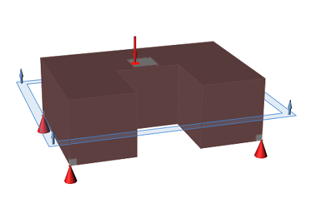
Figure 1. Design Space
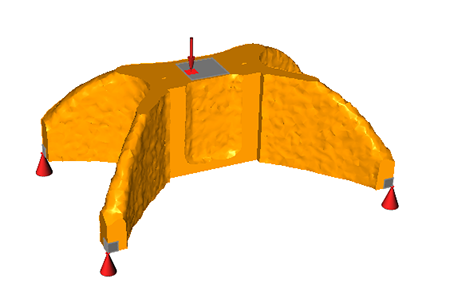
Figure 2. Optimized Shape with Single Draw Direction Applied
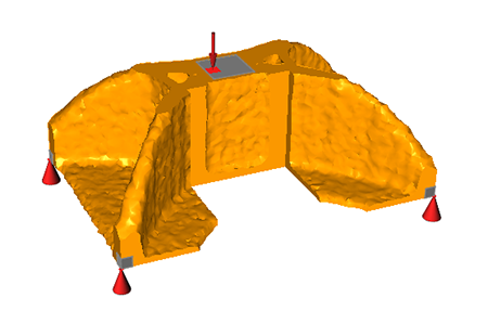
Figure 3. Optimized Shape with Single Draw Direction Applied and No Holes