Run Eigen Analysis
Use the Run Motion Settings on the Analyze Motion tool to define and run an Eigen analysis.
MBD models can be linearized with the purpose of either representing the model in State Space Matrix format or as complex eigendata. The state space matrix representation is usually done in preparation for model exchange; the ABCDE state space matrices can be imported in other simulation software tools such as Altair Compose and Altair Activate.
Eigen analysis can be used to study the stability of the MBD system, and is the calculation of eigenvalues (natural frequencies and damping characteristics) and eigenvectors (mode of vibration associated with each frequency) of the linearized system.
Both eigen analysis and state space matrix representation give the user greater insights about the system, its natural frequencies, and its stability and dynamic properties.
To run an Eigen analysis:
-
Hover over the Analyze Motion tool and click the
Run Settings
 satellite icon.
-
Click the chevron
 to view and define the Eigen Analysis
Settings. (See below for more information.)
to view and define the Eigen Analysis
Settings. (See below for more information.)
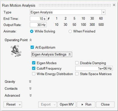
Eigen Analysis Settings
Eigen analysis settings include options for Eigen modes, damping, cutoff frequency, write energy distribution, and state space matrices.
- Eigen Modes
- If checked, Inspire Motion will write a text file with the extension
.eig containing the eigenmodes in complex number form with natural
frequencies and damping ratio. The content of the .eig file can be
viewed in table format by clicking the
 icon on the Animation Toolbar when
reviewing motion results.
icon on the Animation Toolbar when
reviewing motion results. - Disable Damping
- Selecting this option will disable damping in all force elements of the system.
- Cutoff Frequency
- Set a cutoff frequency to skip the visualization of mode shapes related to higher frequencies.
- Write Energy Distribution
- Generate an HTML file with information about kinetic energy distribution
for each of the computed modes. You can review this file by clicking the
icon on the Animation Toolbar when
reviewing motion results. This will open the file in your system
browser. (You can also access the file via the Open Run Folder icon on
the Analyze Motion tool.)
- State Space Matrices
- Generate an ABCDE matrix representation of the system as a text file in OML format. The matrices can be used in a control-system design tool or other system analysis software such as Altair Activate and Altair Compose.
Selection of Plant Inputs and Outputs
The selection of Plant Inputs and Plant Outputs is done automatically in Inspire.
- Any measure (length and angular) will always add kinematic state outputs such
as:
- displacement, velocity, and acceleration for any length measurement
- included angle and included angular velocity for any angular measurement
- Any motor and actuator, when the appropriate Provide Signals To Plant is
checked, will generate kinematic output channels and input states:
- Outputs:
- displacement
- velocity
- acceleration
- desired signal
- Inputs:
- command signal
- override signal to allow control system software to override the motor command signal
- Outputs:
- Torsion springs and coil springs generate the following inputs and outputs:
- Outputs:
- displacement
- velocity
- Inputs:
- stiffness force
- stiffness override switch
- damping force
- damping force override switch
- Outputs: