Run Settings
Use the Run Settings tool to change the default motion run settings.
You can control how long the motion simulation will run, the number of frames in the results output, the type of analysis, and whether to include gravity.
Click the satellite icon ![]() that appears when you hover over the Analyze Motion tool to change the
run settings for the motion analysis.
that appears when you hover over the Analyze Motion tool to change the
run settings for the motion analysis.
Edit the Motion Run Settings
Change the motion run analysis settings using the Run Motion Analysis window.
-
Hover over the Analyze Motion tool and click the
Run Settings
 satellite icon.
- Use the Export button to export the motion model including analysis settings as a MotionView file (.mdl) or MotionSolve py file (.py).
- Units are chosen upon export, but it is good practice to set the preferred model units in the Preferences and then run the model first before exporting.
- Use the Reset > Defaults option to restore all default motion analysis settings for your model.
Basic Settings
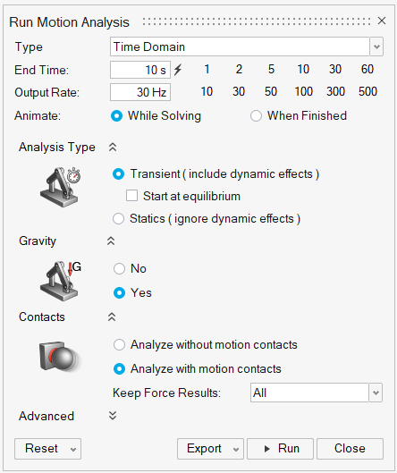
Use the options on the Run Motion Analysis window to define a motion analysis.
Figure 1. Run Motion Analysis- Type
- Select Time Domain to run a motion analysis with respect to time, or Eigen Analysis to run an eigenmode analysis.
- End Time
- The end time indicates how long the motion simulation should run. Holding down the Ctrl key when clicking the Calculate End Time to add 10% more time. This is handy for seeing model behavior after the profile has ended.
- Output Rate
- The output rate controls the number of frames in the results output. Larger numbers give smoother, continuous results, but will animate more slowly.
- Animate
- This option controls whether the model animates While Solving. If you select When Finished, the run will complete faster. If the run is successful, you still have the ability play back the animation by pressing the space bar or clicking the Play button on the animation toolbar.
- Analysis Type (appears for Time Domain only)
- A motion analysis can be either transient, static, or both.
- Transient analysis is used to include dynamic effects in a time-dependent motion simulation. Enable Start at equilibrium to begin from an equilibrium solution first.
- Statics analysis is used to determine the static equilibrium position of your mechanism. For this analysis type, all velocity and damping terms are ignored. This helps you analyze the loading without including dynamic effects.
- Operating Point (appears for Eigen Analysis only)
- The operating point is the position and orientation of the system at which the Eigen analysis should be conducted. See Eigen Analysis Settings for additional information.
- Gravity
- This setting is used to include or exclude gravity from the motion analysis. To include gravity, you must first apply gravitational acceleration using the Gravity tool.
- Contacts
-
- Analyze without motion contacts: Choose this option to exclude motion contacts from the motion analysis.
- Analyze with motion contacts: Choose this option to include motion contacts from the motion analysis.
-
Keep Force Results is a global setting to control the number of contact forces that are stored in the model after motion analysis. Choose All, Region Only or None.
The Region Only option corresponds to the At Region setting for Sum Forces on the Force Explorer. If you choose Region Only or None, be aware that when animating motion results with the Force Explorer, you will only see the level of content you specified for a given contact. For example, if you choose Region Only you will not see the individual (unsummed) force vectors. Likewise, you would not see any of the force vectors due to contact if you select None.
Note: If you want to override the global setting for Keep Force Results and treat a motion contact individually, you can do so from the Property Editor.
Advanced Settings
Click the chevron ![]() next to Advanced to display
advanced options related to solver settings, model checking, and plotting.
next to Advanced to display
advanced options related to solver settings, model checking, and plotting.
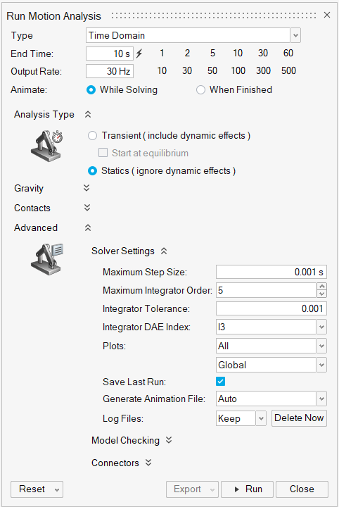
Figure 2. Advanced Settings
Solver Settings
- Maximum Step Size
- The maximum step size the integrator is allowed to take.
- Maximum Integrator Order
- This is the maximum order that the integrator can take. The default value is 5; higher orders lead to higher accuracy, but lower stability. In some applications, like intermittent contact, users may wish to override the default value and set it to a smaller value, like 2 (or 1).
- Integrator Tolerance
- This tolerance represents the maximum absolute error per integrator step.
- Integrator DAE Index
- This is the index of the Differential and Algebraic Equations (DAE) for the solver. The options are I3 (default) or SI1. Choosing SI1 may improve accuracy for a given integrator tolerance, but may also increase run time.
- Plots
- Provides options for what plots to create (all, exclude for parts, none) and what reference frame to use (global, local).
- Save Last Run
- Turn this option off to not include motion results when the model is saved, which will reduce the size of the .stmod file.
- Generate Animation File
- When generating an animation file, you can choose Include all data, Exclude contact data, or None. When enabled, MotionSolve will write a run.h3d file to the run history folder at the end of a successful motion analysis. This file can be used to play back the animation in HyperWorks (via HyperView) or using the stand-alone HyperView Player. The Exclude contact data setting is useful for reducing the overall size of the H3D file when your model has motion contacts, while the default setting (None) prevents the .h3d file from being written for motion analysis.
- Log Files
- Select Keep to retain motion-related solver files from runs. Select Discard to automatically delete the files after a run. Click the Delete Now button to delete the log files on demand.
Model Checking
- Sensors
- Provides options for what modeling checking sensors (all, exclude joint deformation, none) are in effect.
- Deformation Allowed
- Specify the allowed deformation for joints, + or - a tolerance value. The default is 1 mm.
Connectors
Use these settings to override the default behavior of connectors at a global level. By default, all joints have a flexible representation. When the options below are set to Flexible, joints behave as a linear bushing model. When set to Rigid, joints are idealized and do not deform. When the option is set to Virtual, it is very similar to a rigid joint, but with "soft constraint" behavior that is useful for avoiding redundant joints.
- Joint Behavior
- For pins and sliding pins, the default is Flexible.
- Joint Patch Behavior
- For joints on parts that share geometric features, the default is Flexible.
- Support Behavior
- For supports, the default is Rigid.
- Auto Calculate Rates
- By default, the global rates (below) are determined automatically. Disable this option to enter your own rates.
- K: Stiffness rate
- C: Damping rate
- KT: Torsional stiffness rate
- CT: Torsional damping rate
Shortcuts
| To | Do this |
|---|---|
| Abort the run | Press Esc |