Outlet Regions
Outlet regions mimic the behavior of outlet and simple outlet using a combination of removal and extended regions.
Definitions
- Removal region
- Any particle belonging to a list of designated phases will be removed from the simulation if it enters this region.
- Extension
- An extended region in the opposite direction of outlet region's normal where a constant particle velocity or acceleration in the normal direction is enforced.
Outlet Region Types
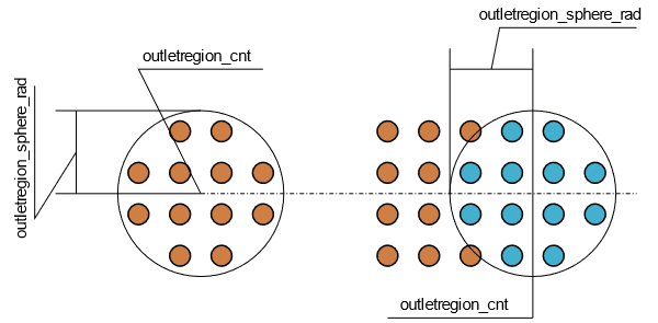
- OUTREG_SPHERE
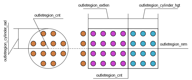
- OUTREG_CYLINDER
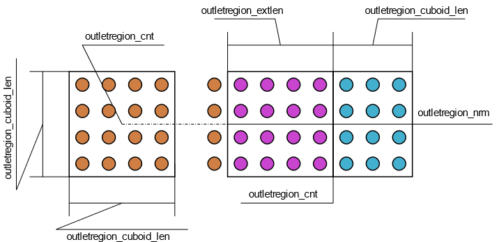
- OUTREG_CUBOID

Figure 1. . Extensions and removal regions for different outlet region types. Particles are color coded as brown for regular particles, purple when they are affected by the extension, and as cyan when residing in removal region. The particle distribution shown in the extension is merely a suggestion and the actual distribution depends on the simulation. Additionally, the removal region will be completely devoid of particles in a real simulation. Continuous lines show extension and removal region borders. (a) Cuboid outlet region (removal and extension). (b) Cylinder outlet region (removal and extension). (c) Sphere outlet region (removal only).

Figure 2. . Cylinder outlet region definitions, color coded as Figure 2. The particle distribution shown is hypothetical.

Figure 3. .
Cuboid outlet region definitions, color coded as Figure 2. The particle distribution shown is hypothetical. Since outlet region normal is defined, the center lies at the interface between extension and removal regions.

Figure 4. . Sphere outlet region definitions, color coded as Figure 2. The particle distribution shown is hypothetical.
| OUTREG | Mimicry | Extension Shape | Normal | Orientation | Movement |
|---|---|---|---|---|---|
| SPHERE | SIMPLEOUTLET | Not applicable | Not required | Not applicable | Static |
| CYLINDER | SIMPLEOUTLET/OUTLET | Cylinder | Required | Global x, y, z | Satic |
| CUBIO | SIMPLEOUTLET/OUTLET | Cuboid | Optional | Global x, y, z | Static |
Time-State Series File
Time-state series (.tss) files are used for outlet regions with time dependent extensions. A .tss file consists of two columns: (1) time and (2) state (signed) magnitude. The state here is either velocity or acceleration, given at times of interest. The solver uses linear interpolation to obtain the state value between given times.
When used to specify velocity, tss values should be all positive. It is not possible for particles to move in the reverse direction of the outlet region normal. When used to specify acceleration, tss values are signed magnitudes. The values may be positive and/or negative. Particles subjected to excessively negative acceleration may obtain velocities in the reverse direction of outlet region normal.
Basic Operation
When used without extensions, outlet regions act as pseudo zero pressure and zero stress boundaries with no backflow. Since the particles are missing neighbors (incomplete support), these conditions are not strictly met, hence pseudo. In a way, this is the same behavior as the one observed for a free surface (void interface).
- Set acceleration:
- Set velocity:
When using acceleration extension type, the extension sets the normal component of particle acceleration to the specified value. The outlet region's normal direction is defined in the cfg. The particle acceleration is free to evolve in directions perpendicular to the outlet region's normal. For particles immediately outside of the extension, the particles in the extension represent a form of outlet boundary with constant acceleration. While a valid form of boundary condition definition in SPH, this definition of boundary is somewhat loose, hence the acceleration felt by the particles immediately outside of the extension is not exactly equal to the value set in the cfg. The pressure immediately outside the extension will adjust itself to support the flow through the extension.
Applying zero acceleration is a special case of acceleration type extension. In this case, any particle entering the extension will maintain its velocity in the normal direction. For a fully developed and steady state flow, this may lead to an accurate representation of zero gradient velocity in the normal direction.
When using velocity extension type, the extension sets the normal component of particle velocity to the specified value. To be more specific, the acceleration is modified in a way to lead to the desired value for the velocity component, once integrated in time. The particle velocity is free to evolve in directions perpendicular to the outlet region's normal. The particles immediately outside of the extension will see this as some form of constant velocity outlet boundary. As mentioned before, this is a somewhat loose form of boundary condition and the velocity felt by the particles immediately outside of the extension is not equal to the outlet region velocity. The pressure immediately outside the extension will adjust itself to support the flow through the extension. Applying zero velocity in velocity type extension will result in a clogged outlet region.
When used with extensions (OUTLET), outlet regions remain unaffected by the component of the external acceleration field of the simulation parallel to the outlet regions' normal. For example, in case of simple gravity and an outlet region with set acceleration, this would mean that the component of gravitational acceleration in the outlet region's normal direction is replaced by the specified acceleration value. In this particular example, this may be interpreted as gravity is not a dominant factor in the outlet region's normal direction for the flow.
- Entering the extension, the velocity of the particle will be dictated by the extension settings. The extension leads the particle toward the removal region (in almost all cases).
- Entering the removal region, the particle is marked for removal. The particle is removed when special movement operations, for example between ranks, out of domain, periodic and outlet, are carried out.
The removal region used in outlet regions is a volume and should not be confused with a surface. This means the particle position should reside within the volume of the removal region for one time step for particle's removal. Simply passing the surface of the removal region does not mean particle removal if the particle goes through the removal region volume. Using too thin of a removal region (approaching a surface) may result in particles simply passing through the outlet region without being removed. In addition to using adequate volume for the removal region, sealing of a conduit-based outlet region with walls would help its proper function.
Outlet regions accept a list of phases to operate on. The outlet region phases have no type restrictions, that is, you may specify fluid and/or solid (wall and/or moving wall) phases. While it is possible to have outlet regions with mixed phase types, it is safer and faster to keep the solids and fluid outlet regions separated. Only the removal region of an outlet region applies to solid phases and the extension is ignored.
Limitations
- Outlet regions do not check for collision with each other.
- Outlet regions do not check for collision with domain boundaries.
- Outlet regions with set acceleration or set velocity type extension overwrite the external acceleration field in the direction of outletregion_nrm.
- Outlet regions do not support arbitrarily oriented state values.
- Outlet regions do not support state profiles.
- Outlet regions do not support backflow.
- Outlet regions do not support setting pressure explicitly.