Aeration-Viscosity Models
Improving torque estimates in nanoFluidX is of high importance. Currently, prediction of accurate absolute values of torque for general geometries has a series of quantitatively varying results.
Namely, some of the industrial partners have reported very good agreement between experiments and nanoFluidX simulations. However, single gear immersed in an oil sump or the FZG 2-gear case show significant differences with respect to results.
Moreover, accurate measurements of torque are extremely difficult to do for a number of reasons, some of which include temperature and viscosity of oil variations during measurements, accurate consideration of constant loads, that is, bearings, sealings, and so on, accuracy limitations of the measurement tools, and similar. However, one of the relevant physical phenomena is the dependency of apparent or effective oil viscosity, the presence of air in the oil bulk, is referred to as aeration-viscosity models.
While nanoFluidX contains a number of numerical improvements to bring you closer to accurate torque predictions, it also incorporates the aeration-viscosity models so as to account for cases where aeration-viscosity effects might be prominent.
Theoretical Introduction
- Is the apparent viscosity of the fluid.
- Is the initial viscosity of oil.
- Is a unitless coefficient.
- Is the volumetric fraction of air in the oil.

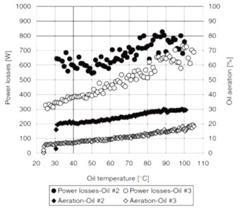
Figure 1. Increase of churning power losses. A function of increasing oil aeration for two different types of oil. bibliography_r.htm#bibliography_r__bibliography_r_fn_yzf_gmc_4gb
As air gets entrapped in oil, the churning becomes more difficult since additional work is wasted on deformation and compression of air bubbles (both macro and microscopic in size).
This effect increases as the viscosity of oil goes down, which in turn results in higher torque (churning losses).bibliography_r.htm#bibliography_r__bibliography_r_fn_yzf_gmc_4gb bibliography_r.htm#bibliography_r__bibliography_r_fn_sjq_gmc_4gb bibliography_r.htm#bibliography_r__bibliography_r_fn_zky_gmc_4gb This is counter-intuitive as you would expect that as the viscosity of the oil goes down, the churning losses would go down too. In reality, the opposite is true, but only if the flow is violent enough to cause sufficient aeration, otherwise the common-sense trends of churning losses dropping with the drop of viscosity apply.
Finally, there is the question of what is the value of , and the answer to that is unknown and it depends on the properties of the oil itself. There is no documented exploration of this parameter in the literature. Therefore, you have to calibrate the value based on existing experiments.
Implementation of nanoFluidX
There are multiple ways to implement the model, especially since the papers that report these effects are not dealing with the topic on a numerical level, therefore there is some ambiguity.
- NOMODE
- Self-explanatory.
- LOCAL
- Each oil particle has its air fraction measured and updated local viscosity accordingly.
- GLOBAL
- Measure the air fraction for each oil particle, then average that with the total number of oil particles and then change the oil viscosity uniformly (for all the particles).
When an oil particle is completely surrounded by oil, it will have an air fraction of 0 ( ). However, when it is fully surrounded by air, and due to the fact that you take the value of the kernel of the owner particle itself, the air fraction would be approximately 0.9 or so ( ). Although, this cannot be treated as a 100 percent accurate volume fraction approach, in principle the method is consistent with the physical idea of measuring the volume fraction.
For purposes of aeration level tracking, when the aeration-viscosity models are enabled, the info file for oil will contain an average aeration level, which is measured by taking the sum of the “volume fraction” of each oil particle, divided by the total number of particles of the oil phase.