MV-8004: n-Post Event
In this tutorial, you will learn how to add a 4-Post event for the Sedan car model, run the model in MotionSolve, and view the simulation results.
The purpose of this tutorial is to show the process of adding an N-Post event, assign the posts input signals to excite the vehicle, and post-process the results.
The n-Post event is used to verify the ride performance of a vehicle and for the correlation process with physical test information. The vehicle is supported on a test-rig by posts attached to the wheels. Input signals drive the posts to excite the vehicle, which can be acceleration, displacements, or forces and moments.
Add Example Sedan Car Model and n-Post Event
-
In a MotionView session, on the menu bar, click to open the Preferences dialog.
- Select MBD-Vehicle Dynamics Tools.
- Click Load.
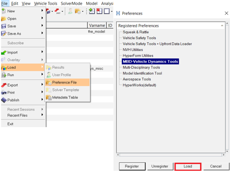
Figure 1. -
On the menu bar, click .
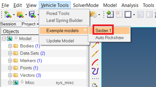
Figure 2.The Sedan car model is displayed in the modeling window.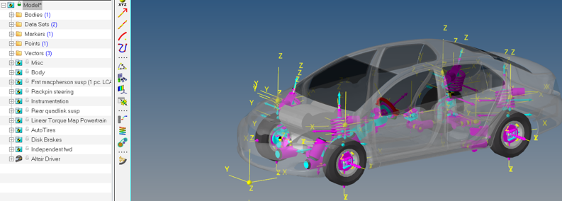
Figure 3. -
On the menu bar, select .
- From the Add Events dialog, use the Type drop-down menu to select the n-PostShaker option.
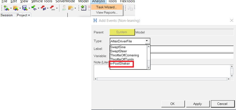 Figure 4. Note:
- The Add Events dialog can also be accessed from the context menu by right-clicking on the Model in the browser.
- The Driver system in the model is necessary to add a n-Post event (or any other Driver event).
The n-Post Shaker event is added to the model. -
In the panel area, review the vehicle orientation.
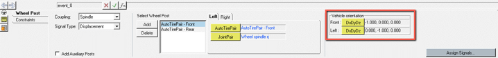
Figure 5.
The n-Post event adds a post for each AutoTire/AutoTirePair in the model. These posts are added based on Vehicle Orientation. While adding the event, the Vehicle Orientation is detected based on the input from AltairDriver System.
If the orientation specified in the AltairDriver is the desired one, there is no need to make changes in the n-Post orientation. However, after adding the n-Post event, if the vehicle orientation must change, the orientations in AltairDriver and in the n-Post event panel should also be updated.
Coupling with Auto Tires - Spindle Coupled
This step will demonstrate how the n-Post event works using the Spindle Coupled method.
Spindle Coupled: The wheel body will be constrained at the wheel center to the post using an in-plane joint with the plane normal to ground.
-
From the Wheel Post tab in the panel, select Spindle
from the Coupling drop-down menu.
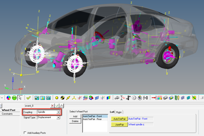 Figure 6.
 -
The n-Post event recognizes the AutoTire Pairs and automatically populates the
entities in the Select Wheel Post section. Check to see if the two AutoTire
Pairs are included and the attachments are defined.
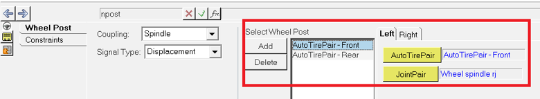 Figure 7. Note:
- The Wheel post connects to the ground by an orientation joint.
- The Wheel Body is connected to the Jack Body by an inplane joint
- The wheel body X and Y directions are restricted using BISTOP Force elements.
Important: Entities created through a n-Post event like joints, bodies, graphics, and points are not able to be edited. -
From the Constraints tab, check the attachments.
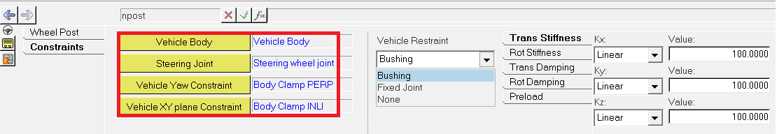 Figure 8. The highlighted attachments are required to aid the driver during static and dynamic simulation of the n-Post event. The Vehicle constraints can be decided based on comparative physical testing setup.
- The Steering Wheel Joint is used to lock the steering wheel motion during the simulation.
- Vehicle Yaw constraint and Vehicle XY Plane constraint are joints used in all vehicle events to ensure proper vehicle attitude after a Static solution.
-
From the Wheel Post tab, select Displacement from the
Signal Type drop-down menu.
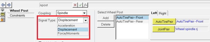 Figure 9. There are three signal types that can be used for the input to spindle coupled arrangement:
- Displacement
- Acceleration: Acceleration is converted to displacement. The signal manager performs the conversion by integrating the acceleration to velocity and the velocity to displacement. At each step, the signal is conditioned by a band pass filters with limits of 0.5 Hz and 1000 Hz.
- Force/Moment:
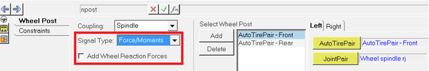 Figure 10.
 If the ‘Add Wheel Reaction Forces’ option is checked, the reaction forces are calculated at the wheels after the static simulation and added to the Z-direction force signal provided. The force signal is applied to the Wheel Post and can be seen in the n-Post Signal Manager.
-
Click on Assign signals to access the n-Post Signal
Manager.
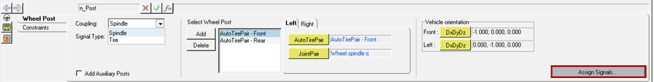 Figure 11.
Assign Signals using the n-Post Signal Manager
The input signal file is chosen by clicking on the folder icon under the ‘Drive File’ header. Supported file formats are .csv, .dac, .rsp and .rpc.
-
In the n-Post Signal Manager, select AutoTirePair -
Front, click on Drive File Z icon and select
FL_disp.csv.

Figure 12. -
Click on the Plot icon
 to view the signal with the given scale and
offset.
to view the signal with the given scale and
offset.
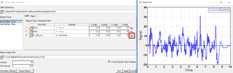
Figure 13. -
Click on the Right tab, and enter
FR_disp.csv in the Z signal field.
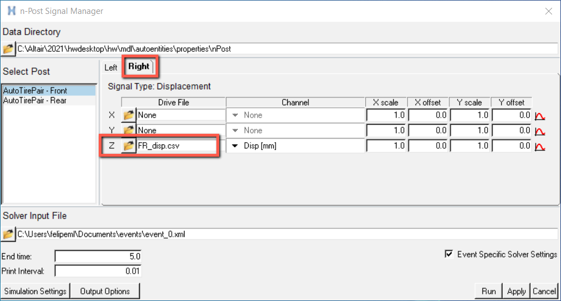
Figure 14.
Run n-PostShaker Event
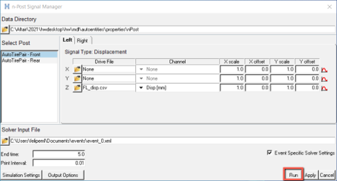
Figure 15.
- Clicking on Apply and closing the signal manager dialog will store the configurations defined.
- Running an event is also possible from the context menu by right-clicking on n-PostShaker event in the browser and in the MotionView Run panel.
- AutoTires are deactivated before exporting the solver deck. AutoTires initial existence will help the driver to decide the number of posts.
Animate and Plot
-
Load the event_0.h3d in HyperView and animate the simulation.
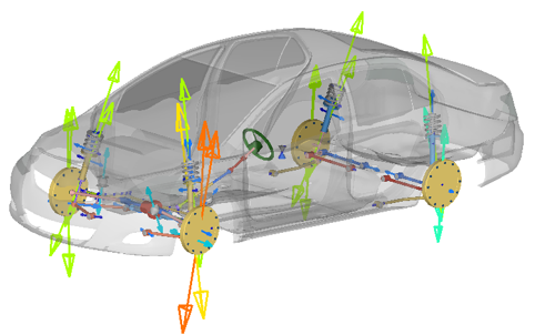 Figure 16.
 -
Load the event_0.abf in HyperGraph and plot the vehicle output signals.
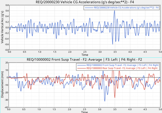 Figure 17. Note: n-Post event is not associated with a report definition, therefore the Automated Reports are not available for this event. You can create your own reports using plot sessions.
(Optional) Coupling with Auto Tires - Tire Coupled
Tire Coupled: The wheel body attaches to the post via a linear stiffness and damping representing the tire. This switch in the tire model happens within the AutoTires.
-
From the Wheel Post tab in the panel, select Tire from
the Coupling drop-down menu.
The n-Post event recognizes the AutoTire Pairs and automatically populates the entities in the Select Wheel Post section.
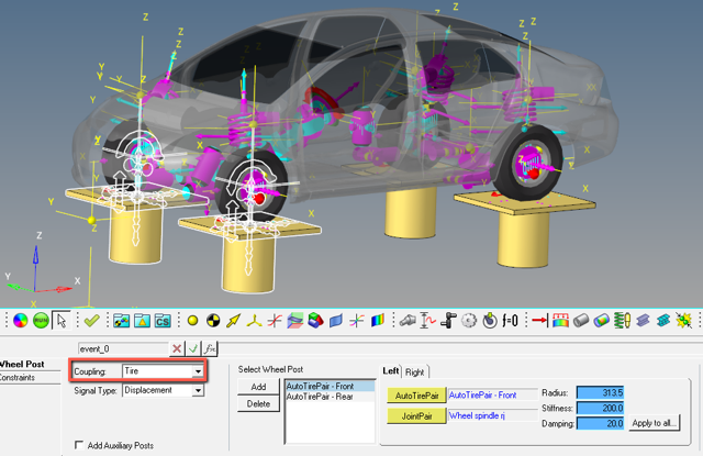 Figure 18.
 - New inputs given for Radius, Stiffness and Damping are shown in the
panel. These parameters are used in an IMPACT function with the exponent
value set to 1.0, to mimic a linear rate spring. The function takes the
following form with parameters plugged
in:
`IMPACT( DZ({mrk_onWheel.idstring},{mrk_onJack.idstring},{mrk_onJack.idstring}),
VZ({mrk_onWheel.idstring},{mrk_onJack.idstring},{mrk_onJack.idstring}),
{ds_actData.real_tireRadius.value}, {ds_actData.real_tireStiffness.value}, 1.0,
{ds_actData.real_tireDamping.value}, 0.001)`
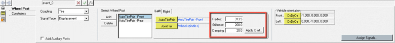 Figure 19.
 - New inputs given for Radius, Stiffness and Damping are shown in the
panel. These parameters are used in an IMPACT function with the exponent
value set to 1.0, to mimic a linear rate spring. The function takes the
following form with parameters plugged
in:
-
From the Constraints tab, check the attachments.
The vehicle constraints in the Tire Coupling method have the same objective as in the Spindle method.
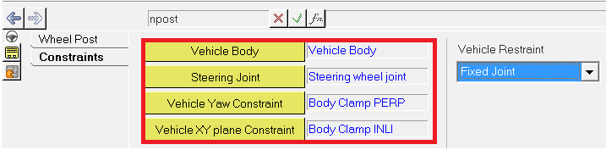 Figure 20.
(Optional) Add an Auxiliary Post
Auxiliary posts may be used to include excitations other than the road surface, such as aerodynamic forces and/or lateral disturbances. The auxiliary posts can be added at any location and the model can have as many posts as needed.
-
From the Wheel Post tab in the panel, check the Add Auxiliary
Posts option check box.
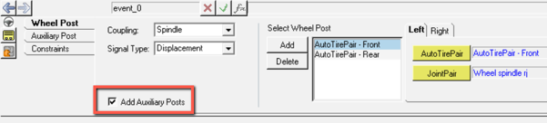 Figure 21.
 -
In the Auxiliary Post tab, select Force/Moment from the
Signal Type drop-down menu.
 Figure 22.
 -
Click on Add to create an Auxiliary Post.
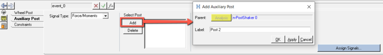 Figure 23.
 -
Select Vehicle Body for Body,
Point_1 for Apply at Point, and
Point_0 for Mount Point.
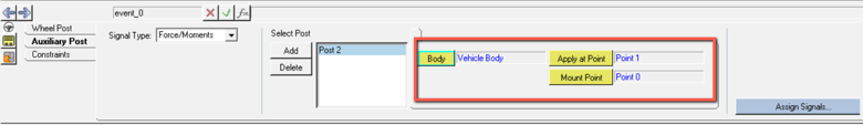 Figure 24. Attachments for each Auxiliary Post consists of Body, Apply at Point, and Mounting Point. The direction of Displacement/Force application is from Mount Point to Apply at Point.
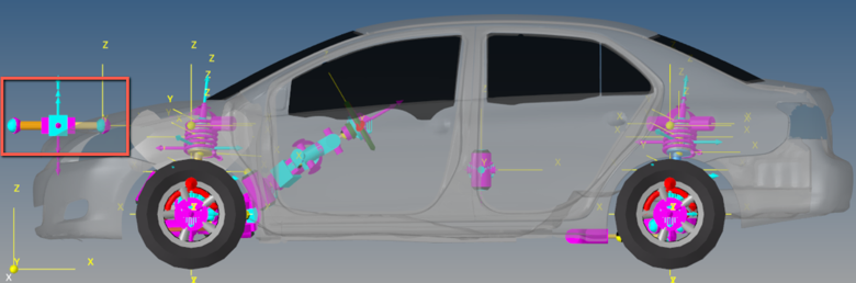 Figure 25. Note:
- A ball joint is used between the actuator tube body and the ground.
- A ball joint is used between the actuator rod body and the vehicle attachment Body.
- A translation joint is used between actuator tube and rod to guide the single directional displacement/acceleration/force inputs.
-
Click on Assign Signal.
The created Auxiliary Post is now shown under the Select post option in the n-Post Signal Manager.
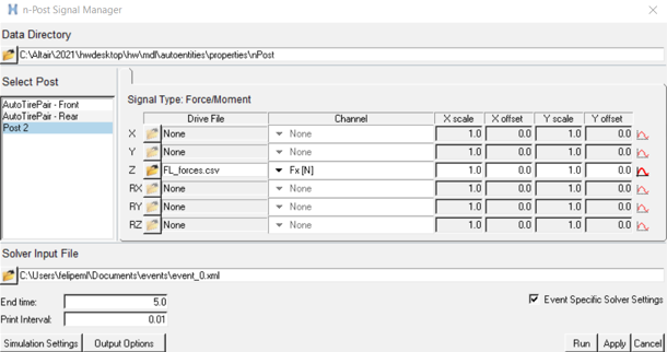 Figure 26.