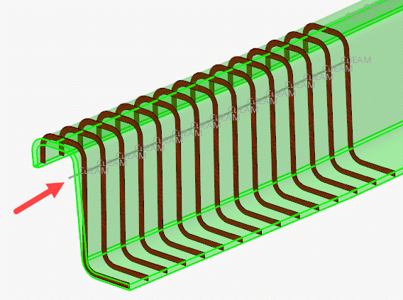
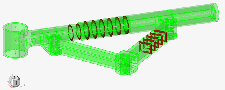
Update 1D Element Properties Using Cross Sections
Use the Section Property tool to update properties assigned to bar2 or rod elements (target) using a cross section on various entities as the source.
- A collection of solid geometries
- A collection of surfaces
- A collection of elements (2D & 3D)
Sectional Property Evaluation Theory
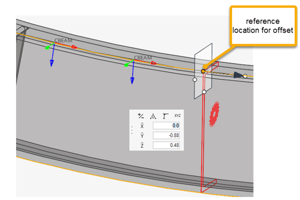
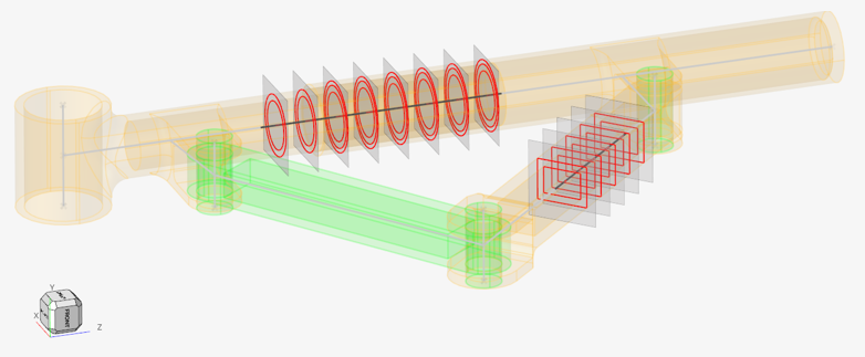
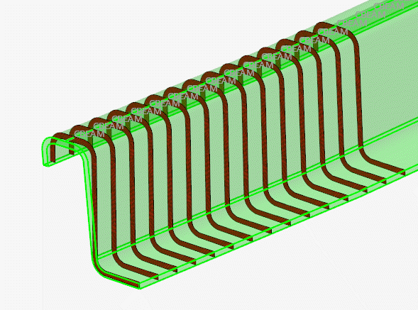
The Section Property tool calculates the intersection between a plane and source entities. It can be a plane per 1D target element or a single cut at a user-defined reference location.
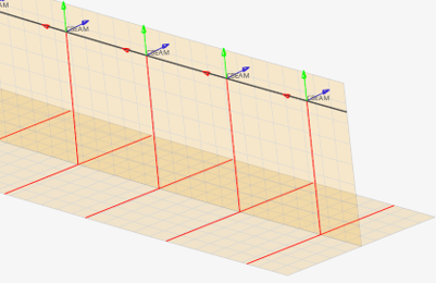 Figure 9. Intersections with shell with thickness |
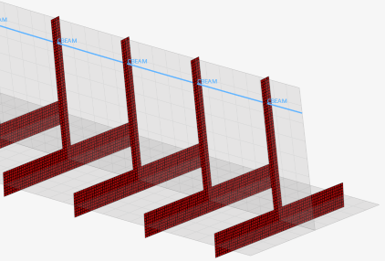 Figure 10. Mesh after section inflate |
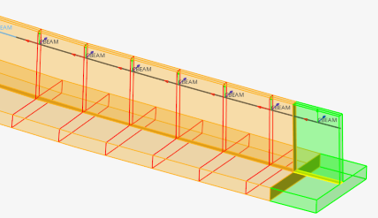 Figure 11. Intersections with solids (geometry) |
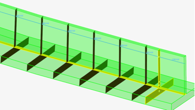 Figure 12. Mesh of solid intersections |
Material info is considered from each intersected entity. If source entities intersected are solids or surfaces, then the material is extracted from the component which holds the intersected geometry. If source entities are elements, then material info is gathered from each element (directly or through component).
Sectional properties are hence calculated following theory as described in: “Analysis and Design of Elastic Beams: Computational Methods, Walter D. Pilkey”
The material neutral axis is calculated along with stiffness terms EIyy, EIzz, GJ, and EA considering local material info. Shear Center and warping properties like torsional constant and warping constant are also calculated.
After sectional properties are calculated accounting for all materials, a regular homogeneous beam property is created referring to a single (homogenous) material and a generic beamsection.
You can specify a target material to be used for homogenization or let the tool auto-calculate the material property using effective young modulus. The beam section area and area moments of inertia are set based on the material's Young modulus to retrieve the same stiffness terms as calculated from the intersected entities.
In turn, if the material is auto-generated, its young modulus is derived from the section product EA and total area A as Eeff= (EA)sec/A. The area moments of inertia are then I=EI/ Eeff; Moments of inertias will deviate from geometric quantities in case of multiple materials, but the section’s Area is correct.
If a target material is provided, then its young modulus will be used; hence all geometric terms A, Iyy, Izz, Iyz may deviate from those calculated by closed form equations for similar geometric shapes.
Orientation and Offset
The elemental system of target 1D elements remain unchanged during the update process.
When a cross section is performed on a 1D element, its local X axis is taken as the section plane’s normal. The beamsection local 2D system (Y, Z) matches with the elemental axis (Y, Z). Sectional properties are hence valid in elemental system as defined. If orientation needs to be adjusted, it is advisable to update the element orientation first (see Orient Bar2 Elements).
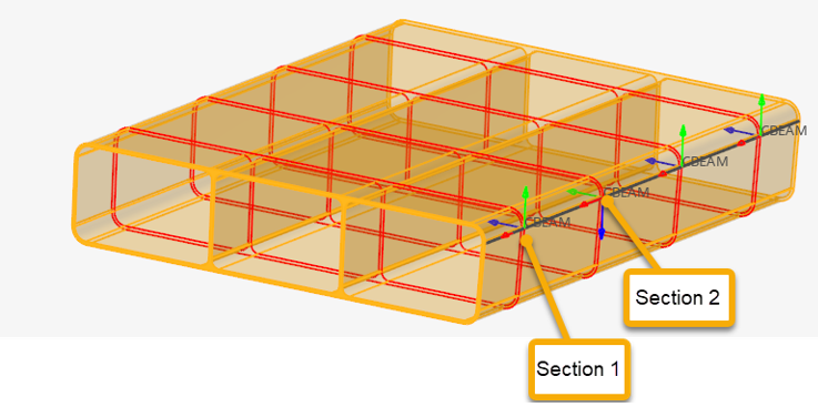
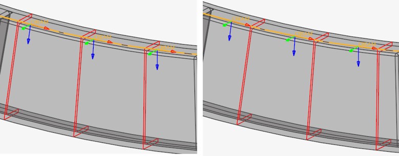
Figure 13. Section cut per element
Since a cut is performed per element in Figure 13, each section has its own local system matching the elemental system, as shown in Figure 14 & Figure 15. The origin of the system, from which Centroid and Shear Center coordinates are saved in the beamsection entity, is taken at the center of the bounding of the section in the local system.

Figure 14. First section

Figure 15. Second section

Figure 16. Calculated section after offset
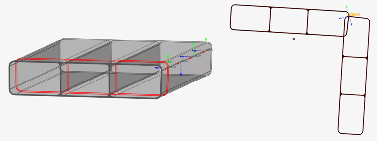
Figure 17. Single section cut on misaligned elements
Materials
If a region has no material assigned, the calculation uses E =1, nu =0, and G = 0.5 by default.
Otherwise, materials are extracted from properties (on elements or components). To account for material info on geometry, it is mandatory to assign a material to the component which holds the geometry. It is important to note that if a geometric component lacks material info, the engine will use defaults as mentioned before. It is fine if no other materials are in use, but might lead to inconsistent results if a mix of default and true materials are used in the same section.
Disconnected Parts
A section cut on a model may lead to disconnected regions. It could be because of separate bodies which are glued or welded, or because section undergoes a hole in model. A valid section needs to be connected to consider it as an equivalent beam section.
In any case, the Section Property tool generates a beamsection with geometric properties like area and second moments of inertia calculated. However, to fully complete the process and calculate shear center position as well as torsional & warping constants, the section need to be “connected”.
The tool provides two options called “weld” and “contact”.
- Welds
- The regions made of thin parts (intersections with 2D elements or surfaces) can be welded based on the line domain proximity (before mesh inflate). The weld option has 3 values:
- Contacts
- All domains like 3D region cuts or inflated domains (Figure 18) that remain disconnected are candidates for auto-contact. Auto-contact will internally generate kinematic equations to glue domains which are in proximity. The contact option has 3 values:
After welding lines and gluing domains, sectional properties are calculated as described above.


