Create and Realize Connectors
Use the tools in the Create tool set to create connectors, assign controls, and realize.
-
Navigate to the Connectors ribbon then select any of the
tools in the Create tool set to define the associated connector type.
- Point
- Fastener
- Line
- Area
-
On the guide bar, click
 to define connector options.
- Use the selector on the guide bar to choose an entity type, then select features on which to create connectors.
-
Use the options in the microdialog to further define
the connector.
The following options are available for all entity types and tools.
Option Description Move/Morph (  )
)Relocate sections or the whole connector to a different position Link Edit (  )
)Opens a dialogue that allows you to adjust the link detection logic. Show/Hide Projections (  )
)Show and hide the pre-projections that indicate where the connector will connect to. Other options are dependent on the entity type and selected tool.Option Description Trim (  )
)Split the connector at a selected position. Available for node list, line, element, and surface selection.
Partition (  )
)Partition the seam connector if any part of that connector does not have projections. Only available for the Line tool.
Pitch and Density - Pitch (
 )
) - Adjust the number of significant points along the connector line by given spacing.
- Density (
 )
) - Adjust the number of significant points along the connector line by a number.
Available for node list and line selection in the Point and Line tools.
Line Interpolation - Straight line (
 )
) - A straight interpolation line is created between the
selected nodes.
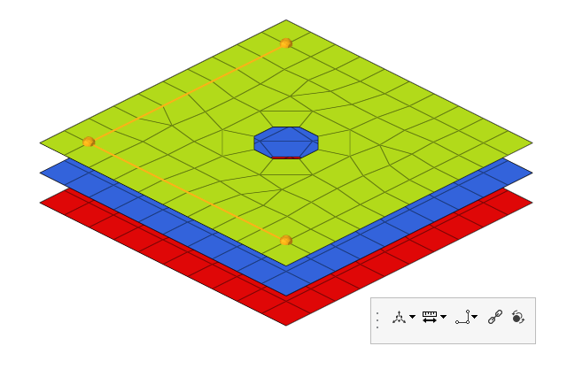
Figure 1. - Interpolated line (
 )
) - A smoothed interpolation line is created between the
selected nodes.
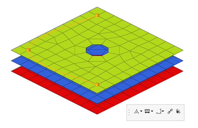
Figure 2.
Available for node list selection in the Point and Line tools.
Line Creation - None (
 )
) - Leave the line selections separate.
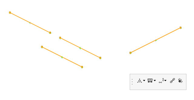
Figure 3. - Combine Smooth (
 )
) - Combine selected lines with an interpolated line.
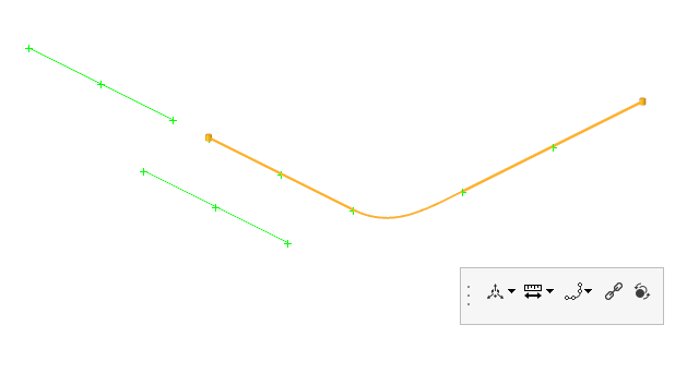
Figure 4. - Combine Straight (
 )
) - Combine selected lines with a straight line.
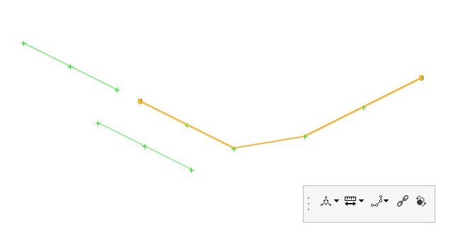
Figure 5. - Mid Line (
 )
) - Generate a midline between selected lines.
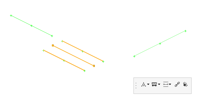
Figure 6.
Only available for line selection.
Remesh (  )
)Remesh the connector surface. 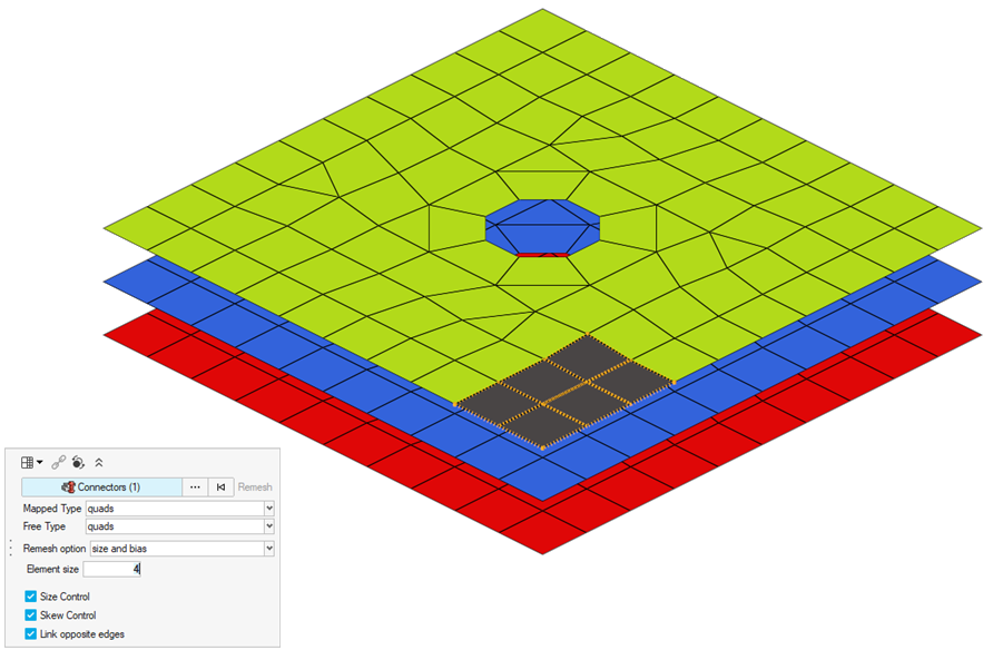
Figure 7.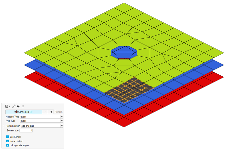
Available for any selection type in the Area tool.
- Pitch (
-
Use the drop-down menu on the guide bar to assign a
control to the connector.
Choose a previously defined control or click Create New to open the Control Manager and define a new control. If you select Undefined, the connector will be created without a control.
By default, an assigned control is realized.
-
On the guide bar, click one of the following:
 - Save changes and stay in the tool
 - Save changes and close the tool
 - Exit the tool without saving changes
Auto Point
Create weld points at a predefined pitch distance so that the model build process can continue without the need to wait for the published weld data from CAD. The Auto Point tool is useful when working with elements, not geometry.
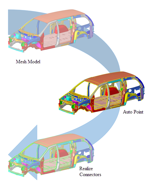
Figure 8. . Starting with a CAD model, the Auto Point tool creates unrealized connectors (yellow) which can then realized via the Point tool.
-
From the Connectors ribbon, Point tool group, click the Auto
Point tool.

Figure 9. -
Select the components to automatically add connectors to.
All selected components receive connectors with the same qualities to help you perform a blanket application of connectors – using the same pitch – to all components that need them as a single operation. Be wary of simply selecting the whole model, however, as this could result in undesirable actions, such as adding welds to a car's tires.
-
Click
 on the guide bar and define
the following options.
- Consider closed shell thin solids
- Use shell meshes that enclose a volume (some small gaps are allowed) as input.
- Create in middle
- Create connectors in the middle of the found flanges.
- Combine spots to lines
- Combine a series of spot connectors into a spot-line connector.
- Maximum number of layers field
- The maximum number of layers for the connector to add.
- Search distance
- The distance to consider between components.
- Spot pitch distance
- The distance between each connector.
- Spot pitch end offset
- The distance from the end of an edge/flange to the connector.
- Distance from free edge
- The distance from the free edge to the connector.
- Distance from feature edge
- The distance from feature edge to connector.
- Feature angle
- The angle used to segregate the model into faces that are planar within its specified value.
- Max deviation from avg dist (%)
- the average distance that can be calculated based on the
estimation that the distance between two flanges does not change
too much in the areas where connectors should be placed.
If the distance at the position where a connector is planned exceeds the given deviating value, no connector will be created at that position.
This segregation is used to identify where auto point connectors are placed. For example, faces found to have significant topological complexity are not used to create auto point connectors.
Note: By reducing its value, the complexity of some of these faces is generally reduced. Of course, flat regions are unaffected by the parameter. - Exclude holes with width less than
- Filter holes from the flange search if under a defined width.
-
Click
 on the guide bar.
The created output is connectors with the appropriate spacing and other associated parameters. The connectors are in the unrealized state.
Auto Line
Use the Auto Line tool to identify locations to create line connectors between components and parts. This process works on 2D geometry and mesh.
-
From the Connectors ribbon, Line tool group, click the Auto
Line tool.

Figure 10. - Select the parts to automatically add connectors to.
-
Click
 on the guide bar and define
the following options.
- Search distance
- The distance between the parts.
- Minimum length
- The tolerance for the smallest connector.
- Holes exclusion radius
- Filters holes from the flange search if under a defined width.
- Spacing
- Sets a spacing value on the connector.
- Create internal seams
- Creates connectors within a part if able.
-
Click
 on the guide bar.
The created output is connectors with the appropriate spacing and other associated parameters. The connectors are in the unrealized state.