Streamlines Graphical Manipulators
Streamlines graphical manipulators allow you to scale, translate, or rotate the streamline rake that was used to create streamlines (defined by seed nodes on a line, plane, or area).
Line Manipulator
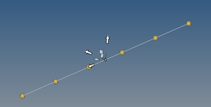
The Line manipulator is available in the Streamlines panel for Line rakes only.
Figure 1.
The Line manipulator is a line with two handles at the end points and one at the center point. A triad is displayed once a handle is selected so that the particular handle can be moved in a specific way.
If no nodes are specified prior to adding the Line rake, the graphical manipulator is created at the center of the model. When nodes are picked prior to adding the Line rake, the end points of the graphical manipulator will match N1,N2. When coordinates are specified prior to adding the Line rake, the end points of the graphical manipulator will match the coordinates entered. The Line rake outline coincides with the Line manipulator, and seeds will show over the manipulator in areas where the manipulator is not falling within the displayed components of the model.
The center point can be freely dragged anywhere in space. The length and orientation of the line will remain unchanged as the manipulator is moved as a rigid entity. In addition, the end points of the manipulator will move identically to the center point (same translation).
Any of the following will result in an update of the associated end point: a mouse drag in the graphics (free movement), an adjustment of coordinates in Streamlines panel for the corresponding rake, or the selection of a node. This update will affect the overall length and orientation of the manipulator, as well as the location of the center point. The other end point will remain unchanged during this process.
Once streamlines have been generated for a rake, any manipulator use will force a regeneration of streamlines upon release the left mouse button (as long as the Auto-generate streamlines option is activated).
Two Directional Manipulator
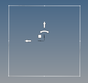
The Two Directional manipulator is available in the Streamlines panel for evenly distributed Area rakes only.
Figure 2.
The Two Directional manipulator is a rectangular planar area encompassing the component selected (or its projection on the plane) with corner and mid-side handles, arrows, and a square handle.
Each arrow can be freely dragged along a straight line. The entire rectangular area will be translated accordingly, while its size and shape will remain the same. The arc arrow can also be grabbed to allow for the rotation of the rectangular area around the normal to the plane. The square handle can be freely dragged on the plane of the area to reposition the rectangular area.
In addition, the mid-side handles can be dragged feely to increase/reduce the dimensions of the rectangular area. As the handle is moved the entire side is translated, resulting in a size change for the connected sides, while the opposite side remains fixed in space. The corner handles be dragged freely on the plane of the area to increase/reduce overall size of area; the two connected sides will follow the dragged corner, while the opposite corner remains stationary. All of the other sides and handles will update accordingly.
As the manipulator is used to move or resize the rectangular area; seeds are updated to show only for the intersection of the component with the area.
Local X defines the number of columns, while local Y defines the number of rows.
The graphical manipulator is restored to its previous state whenever the Evenly distributed option check box is checked or unchecked. The manipulator and rectangular area are removed whenever the Evenly distributed check box is unchecked and the settings are saved.
Three Directional Manipulator
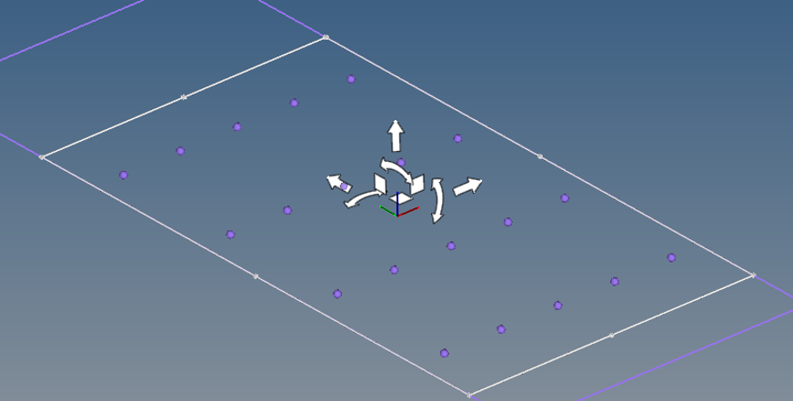
The Three Directional manipulator is available in the Streamlines panel for Plane rakes.
Figure 3.
The Three Directional manipulator is a rectangular planar area with corner and mid-side handles, arrows, and square handles.

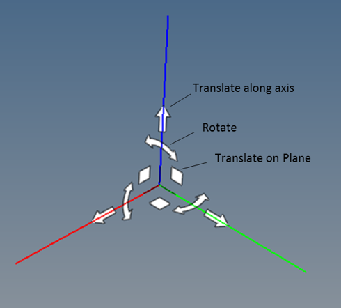
Figure 4.
The center point of the manipulator can be dragged freely anywhere in space. The rake outline receives the same transformation so that the manipulator remains centered. The section cut is dragged in its normal direction, while the manipulator is moved on the plane of the section based on the movement of the mouse. Each arrow can be freely dragged along a straight line; only the manipulator's location on the section plane will change, unless an arrow normal to the section is the one being dragged. The arc arrows can be grabbed to allow the rotation of the section cut around the normal to the plane. The square handles can be freely dragged in space to modify the location of the section cut. Moving the manipulator in the plane of the section does not affect the location of the section cut itself, simply the base location of the manipulator.
The mid-side handles can be dragged freely to increase/reduce the dimensions of the rectangular area. As the handle is moved the entire side is translated, resulting in size change for the connected sides, while the opposite side remains fixed in space. The corner handles be dragged freely on the plane of the area to increase/reduce overall size of area; the two connected sides will follow the dragged corner, while the opposite corner remains stationary. All of the other sides and handles will update accordingly.
As the graphical manipulator is used to move or resize the rake outline - the seeds will follow the rake outline regardless of whether or not they intersect the model.
Local X defines the number of columns, while local Y defines the number of rows.