HM-3210: Create a Hex-Penta Mesh Using Surfaces
For some analyses, it is desirable to use a mesh of hexahedral and pentahedral elements. This is especially true for parts which have a large thickness compared to the element size being used, or for parts that have many features and/or changes in thickness. Castings or forgings are good examples.
- Create solids using different functions
- Check and fix improper model connectivity
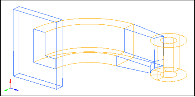
Figure 1.
This exercise uses the arm_bracket.hm file, which can be found in the hm.zip file. Copy the file from this directory to your working directory.
Open the Model File
In this step you will open and review the model file, arm_bracket.hm.
- Start HyperMesh Desktop.
- From the menu bar, click .
- In the Open Model dialog, open the arm_bracket.hm model file.
Mesh the Base
In this step you will mesh the top surface of the base, including the L-shaped surface.
-
Shade the model's geometry and surface edges by clicking
 on
the Visualization toolbar.
on
the Visualization toolbar.
-
Select the surfaces on the top of the base, including the L-shaped surface at
the intersection of the base and the arm.
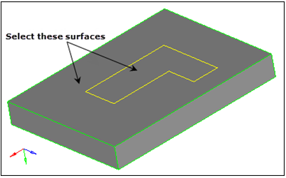
Figure 2. -
Click mesh.
The selected surface is meshed.
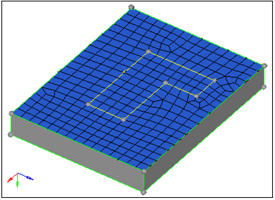
Figure 3.
Create Layers of Hex Elements
In this step you will create layers of hex elements for the base.
-
Click offset+.
The hexa mesh is created.
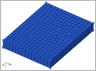
Figure 4.
Prepare the Display for Meshing
In this step you will prepare the display for meshing the arm's curved segment.
Create a Node
In this step you will create a node at the center of the arm radius.
The first segment of the arm can be meshed using the Spin panel. This requires a node to be selected as the center point of rotation. In this step, you will use the Distance panel, 3 nodes subpanel to create a node that will be used as the center point of rotation.
-
While pressing the left mouse button, move it over the curved line as indicated
in the following image, and then release it when the cursor changes to
 .
HyperMesh highlights the line.
.
HyperMesh highlights the line.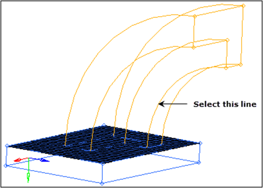
Figure 5. -
Click circle center.
The node is created at the center.Note: You will use this node in the next step when you mesh the arm.
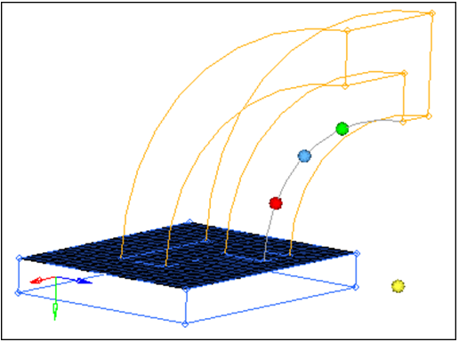
Figure 6.
Create Hexa Elements Using Spin
In this step you will create hexa elements in the curved portion of the arm using spin.
-
Select the plate elements within the L-shaped cross section of the arm as
indicated in the following image.
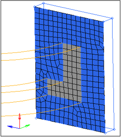
Figure 7. -
Return to the main menu by clicking return.
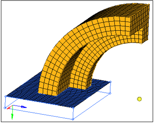
Figure 8.
Create Faces on Hex Elements
In this step you will create faces on hex elements.
-
Shade the model's elements and mesh line by clicking
 on the Visualization toolbar.
The graphics area now displays the elements in the ^faces component.
on the Visualization toolbar.
The graphics area now displays the elements in the ^faces component.
Prepare the Display for Meshing
In this step you will prepare the display for meshing the second arm segment.
Mesh L-Shaped Surfaces
In this step you will mesh the L-shaped set of surfaces between the arm_straight and boss components.
-
Select the three surfaces lying on the intersection between the arm_straight
and boss components as indicated in the following image.
Note: These surfaces are all in the arm_straight component.
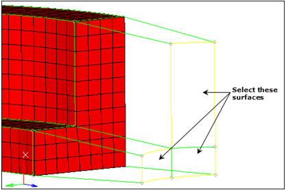
Figure 9. -
Adjust the density of each edge to obtain a mesh that matches the following
image.
Note: This mesh pattern matches the mesh pattern at the intersection of the two arm segments. This is necessary for the next step.
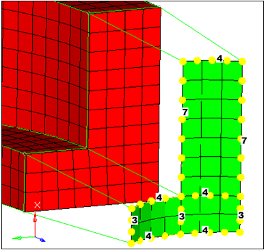
Figure 10.
Use Linear Solids to Build the Mesh
In this step you will use linear solid to build the mesh between the two set of shell elements.
-
Select the ^faces elements lying on the intersection
between the first and second arm segments as indicated in the following
image.
Note: Quickly select all of the necessary elements by selecting one of the elements and then clicking from: elems >> by face.
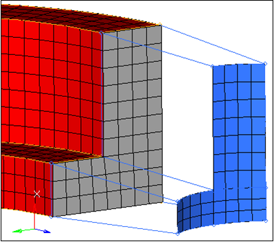
Figure 11. -
Select three nodes on the "to element" that corresponds to the "from element"
with the three "from nodes" as indicated in the following image.
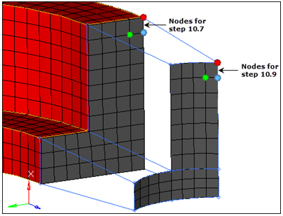
Figure 12. -
Click solids.
The mesh is created.
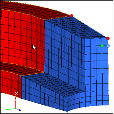
Figure 13.
Prepare the Display to Mesh the Boss
In this step you will prepare the display for meshing the boss.
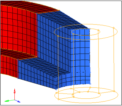
Figure 14.
Create a Shell Mesh
In this step you will create a shell mesh on the bottom of the boss.
-
Select the five surfaces on the bottom face of the boss as indicated in the
following image.
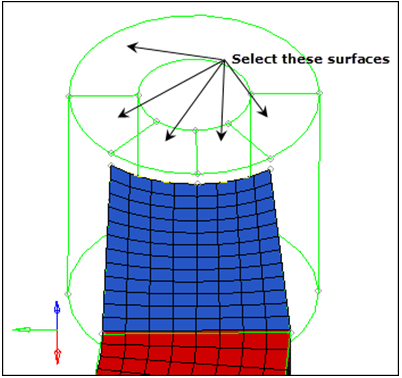
Figure 15. -
Adjust the density of each edge to obtain a mesh that matches the following
image.
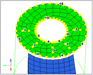
Figure 16.
Project a Node
In this step you will project a node to the bottom face of the boss.
-
Select the line on the boss's top face as indicated in the following
image.
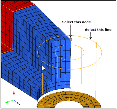
Figure 17.
Generate Hexas Using Solid Map Panel
In this step you will generate hexas for the boss using the Solid Map panel.
-
Select the top surface of the boss as indicated in the following image.
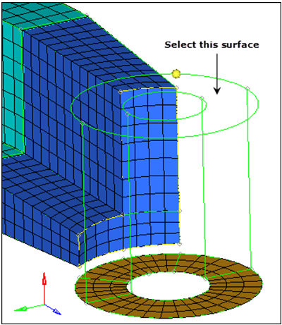
Figure 18. -
Select the 13 nodes as indicated in the following image, to define the exact
location of the solid element layers.
Note: A total of 13 nodes should be selected, starting at the boss mesh, and then using all of the nodes along the edge of the arm_straight component, ending with the node projected to the top of the boss.
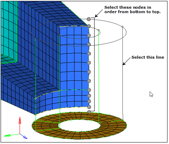
Figure 19. -
Click mesh.
HyperMesh creates the elements and completes the mesh on this part.
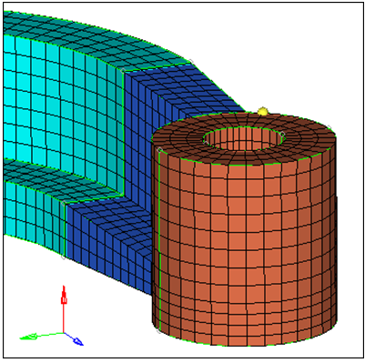
Figure 20.
Check Connectivity
In this optional step you will check the connectivity of the model.
-
Click near the cutting plane, hold the left mouse button down, and move your
mouse back and forth.
The cutting plane moves through the model, allowing you to see if any face elements exist on the interior of the model.Note: You should see that there are face elements interior to the model, between the boss and arm. You need to perform some corrections on the connectivity.
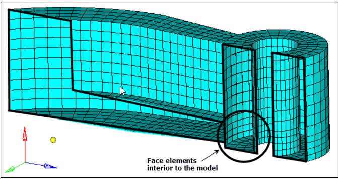
Figure 21.
Correct Connectivity
In this optional step you will correct the connectivity of the model.
-
Display the model's elements as transparent by clicking
 on the Visualization toolbar.
Recheck Connectivity
In this optional step you will recheck the connectivity of the model.
Save Your Work
In this optional step you will save your work.