Composite Definition
Composite shell model definition.
- Ply-based model. Refer to Ply-Based Shell Modeling for further details.
- Zone-based model. Refer to Zone-Based Modeling for further details.
Ply-Based Models
Ply-based modeling entities.
Plies
- Manually from the Composite Browser
- Conversion from zone-based models using the Aerospace Composite Absorb Tool
- Imported from a spreadsheet
- Imported from external composite data like CATIA or FiberSim.
For more information, refer to Plies.
Uni-Directional
Uni-directional plies should be modeled layer by layer using ply entities. The material assigned represents properties homogenized at the ply level.
Woven
| Homogenization Scale | Comment |
|---|---|
| Homogenization of matrix, tows in warp and weft directions. This scale is supported by the homogenized weave ply type. | Impractical to drape - any deviation from θ=90° is new
anisotropic material. Cannot distinguish between ply level fiber and matrix direction results. |
| Homogenization of matrix and tows in just one direction. This scale is supported by the unidirectional weave ply type. | Weave modeled internally as four uni plies with ¼ T. The
stacking sequence is [θ/ θ+90/ θ+90/ θ]. Same material when θ changes. HyperMesh also uses this methodology when importing woven plies from external composite data. |
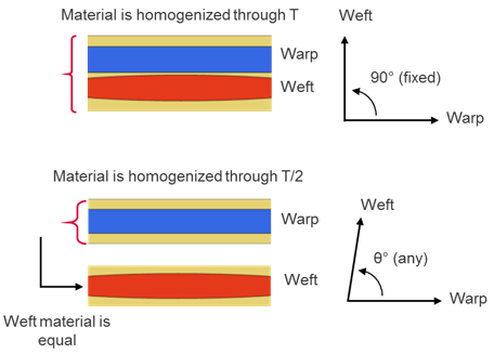
Figure 1.
Core
Core plies should be modeled using the core ply type. Typically, core plies have ramps. The spatially varying thickness of the ramp areas is managed in the drape table when the core ply type is selected. Source data for this ply type is typically solid geometry which is realized to the mesh using ply realization.
Wound
Wound plies should be modeled using the wound ply type. Each wound ply in HyperMesh represents a wound layer at a given winding angle in manufacturing simulation. The spatially varying details of the ply, including thickness changes, number of tows through thickness at a given element, and orientation are abstracted to the drape table. The nominal ply thickness should be the thickness of the tow material product and the nominal ply orientation should be the winding angle. This ply type should be defined in manufacturing simulation and imported as a ply-based .fem into HyperMesh.
Laminates
One ply laminate or interface laminate per physical part is typically defined. Ply laminates are used for composite panels and plates without T junctions or other complex geometry. Interface laminates are used in conjunction with sub-laminates to model complex parts, typically with T junctions. For example, an I-beam.
For more information, refer to Laminate Entities.
Ply-Based Properties
Properties for ply-based models are used as templates. The attributes of the property, offset, non-structural mass, and so on, assigned to component(s)/element(s) are used when final zone-based properties are generated by HyperMesh. If the solver is OptiStruct or Radioss, this definition is formalized – PLY and STACK (Laminate) cards define the layers at each zone and the property defines the additional solver-specific attributes.
- OptiStruct and Radioss require ply-based properties to be assigned. This contains typical solver-specific property information like offset, but composite layers are managed by plies and laminates.
- Other solvers require a standard zone-based composite property to be assigned to elements contained in the plies of a laminate. Any specific solver attributes should be set in this property. Typical zone-based layers data does not need to be entered as it is maintained by the ply-based model. Upon realization of the laminate, zone-based solver properties will be automatically generated.
| Solver | Property |
|---|---|
| OptiStruct | PCOMPP (ply-based cards are part of the solver – zones do not need to be generated) |
| Radioss | PCOMPP (ply-based cards are part of the solver – zones do not need to be generated) |
| Nastran | PCOMPP (Option to realize to PCOMPG/PCOMP) |
| Abaqus | *SHELL SECTION (COMPOSITE) |
| ANSYS | SECTYPE SHELL |
| LS-DYNA | *PART COMPOSITE (on HyperMesh Component entity) |
Zone-Based Models
Zone-based modeling entities.
In addition to generation from the realization of a ply-based model, zone-based models can be created manually. Instead of specifying ply, laminate and template property entities, zone-based solver properties should be defined for each zone of constant thickness.
Offsets
Offsets determine the location of the laminate relative to the mesh.
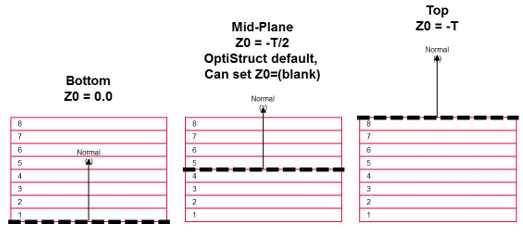
Figure 2.