An introduction to composites terminology and modeling methods.
Terminology
Composite modeling terminology.
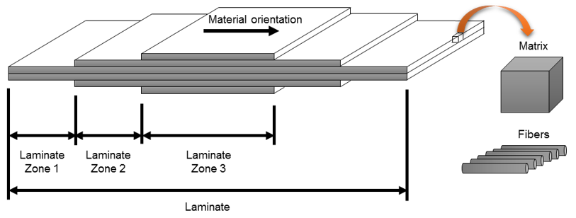
An individual composite part constitutes one laminate:
Laminates are made by stacking plies in a given sequence
Plies are made up of two or more constituents (typically fiber/matrix)
Laminate zones are areas of constant thickness within a laminate
Reference orientation defines the common orientation fiber directions are
rotated from
Figure 1.
Modeling Methods
Composite modeling methods.
Shell-based modeling methods for composites include Ply-Based Shell Modeling and
Zone-Based Shell Modeling.
Ply-Based Shell Modeling
Ply-based modeling.
Ply-based modeling provides an FEA methodology which is consistent with the composite
manufacturing process. The ply-based modeling entities replace, and can generate,
typical solver zone-based composite properties.
A valid ply-based model contains the following entities:
Laminate(s)
Typically, one laminate per physical part is defined. Primarily,
laminates contain the stack of plies. Additionally, laminates specify
symmetry and repeats of plies within a laminate, along with information
that can manipulate the ABD matrices.
Plies
Plies define the material, thickness, orientation (from reference on
element/property material direction), shape (Elements, or element sets
if FEA-based. Lines, surfaces or solids if geometry-based), and ply type
(the material product of the ply).
Template Property
If user profile is OptiStruct, a PCOMPP is
used. If another user profile is selected, a standard zone-based
composite shell property is used. The property defines typical solver
specific attributes like offset and non-structural mass. Layer
information does not need to be entered. It is automatically populated
from the defined plies and laminate.
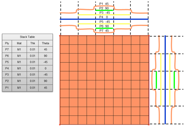
Consider the following composite part which is made up of 1 laminate, 7 plies and 1
template property: Figure 2.
Ply-based models can optionally be used to generate zone-based shell models,
continuum shell, and solid models.
Zone-Based Shell Modeling
Zone-based modeling.
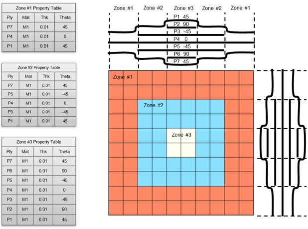
Zone-based models define a table of layer properties at each zone of constant
thickness. The layers on each property contain similar information to the HyperMesh ply, but do not explicitly convey information about
the shape of the as manufactured ply. Some solvers do provide the ability to define
a “global” id/name, which specifies how layers connect from zone to zone. Figure 3.