Edit Module
To manage any of the modules shown in the Assembly Browser, right-click on a module and select Edit Representations. This opens the Edit Module tab, and the Representation sub-tab is shown.
Managing Representations
- CAVITY
- A finite element model that contains only fluid elements.
- CMS
- An H3D or OP2 based component modal synthesis model.
- CDS
- An H3D based component dynamic stiffness model.
- FE
- Typical detailed finite element models.
- DMIG
- DMIG based model files in ASCII format.
- FRF
- A model containing frequency response functions.
- LP
- A lumped parameter model is a simplified 1D finite element model that represents dynamic behavior a more details model.
- MODAL FE
- A finite element modal model that contains spring/damper/spoint/mpc elements.
- PLOT FE
- A finite element model that contains PLOTEL, PLOTEL3 and PLOTEL4 elements.
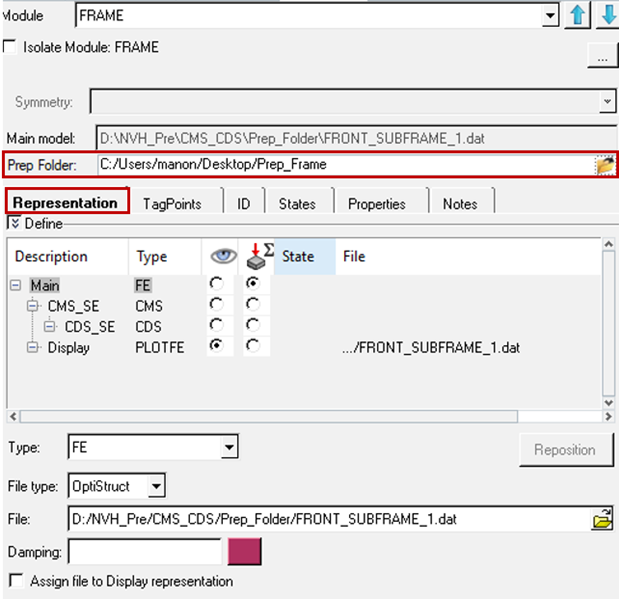
Figure 1.
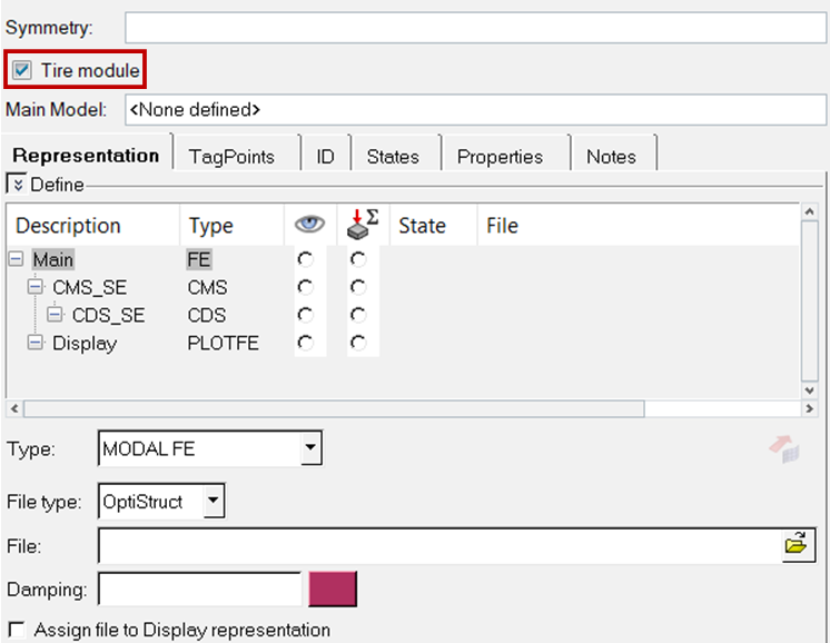
Figure 2.
Right-clicking the white space will give you the options to add, remove, or edit the description of the selected representation.
A file assigned to the root representation can be optionally auto-assigned to be a Display representation (PLOTFE type) simultaneously by checking the Assign file to Display representation checkbox.
A representation can be auto-selected to be the Display representation by checking the Set as Display, load and extract TagPoints checkbox. This will be followed by the file being imported into the 3D graphics window and TagPoints defined in the file extracted.
There is an option to specify tire module. If Tire module is activated, only two types of representations can be assigned to the module. This is to handle the tire specific workflows of creating, editing CDTires, patch points management, positioning, and so on.
Once all representations are defined, click the Assembly Browser tab to review the assembly hierarchy with active Display and Analysis representations.
You can also specify Prep Folder for the module. This prep folder is a folder where you have read/write permissions to save the modified representation files.
Cavity Representation and Coupling Options
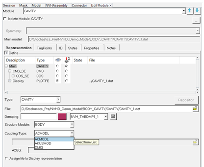
Figure 3.
Define Test FRFs (UNV) as module representations
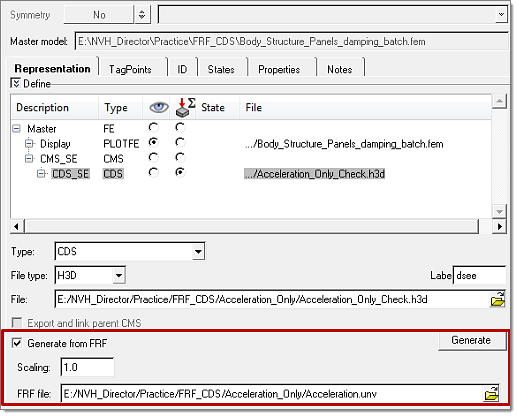
Figure 4.
- Modal model review and parameter modifications
- These features allow for the review of modal model parameters of reduced model representations (both CMS-SE and Modal-FE) and modifying them. This will help you in understanding the effect of changing these parameters on NVH responses, without generating reduced models with necessary modifications.
- The related list of features for CMS-SE are:
- Validate SPOINT ids
- Allows you to manage ID conflicts between SPOINT IDs of CMS-SE reduced model and module ID ranges.
- Assign damping
- Assign existing damping/add component damping to existing damping in CMS-SE. By default, existing damping while creating CMS-SE is used. There is also an option for adding damping to existing component damping.
- Modal parameters review and modification
- Use the ascii option to read modal parameters information from an .ascii file (_dmig_dv.inc) generated during the CMS-SE solver run. Information related to the modal is populated for review. Select Mode to modify the parameters. This will activate the Edit fields to modify frequency and damping values. There is also an option for the mode to be Grounded. Save and apply the changes. This modified information is then exported to the solver deck.
- Animate Modes
- Select a mode and click Preview Modes
 to visualize the mode shapes. The
Modal Animation dialog opens to review mode shapes.
to visualize the mode shapes. The
Modal Animation dialog opens to review mode shapes.
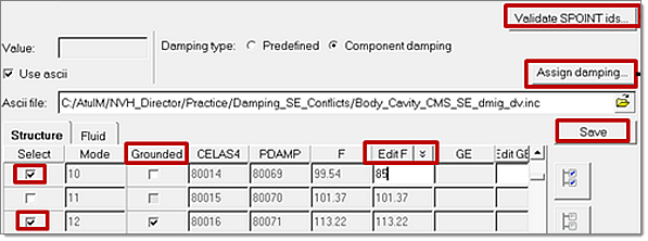
Figure 5.
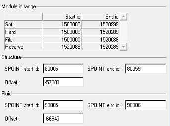
Figure 6. Clicking Validate SPOINT IDs Opens this Dialog
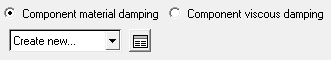
Figure 7. Clicking Assign Damping Opens this Dialog
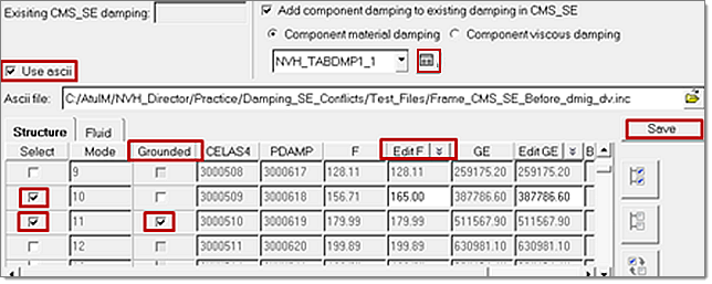
Figure 8.
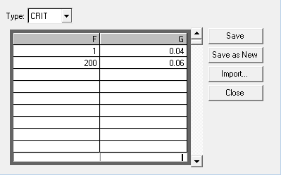
Figure 9. Clicking the
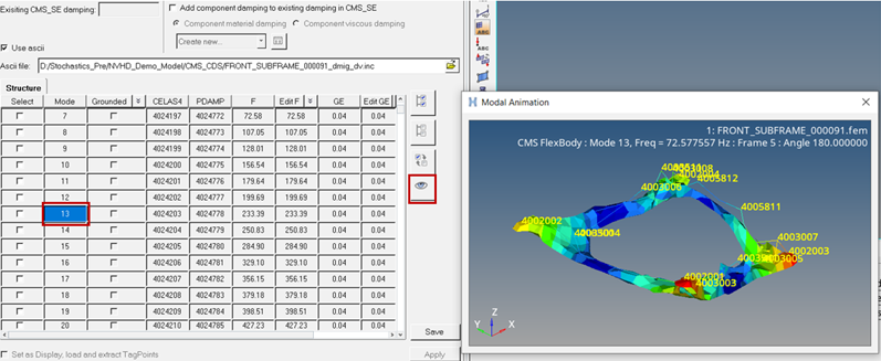
Figure 10.
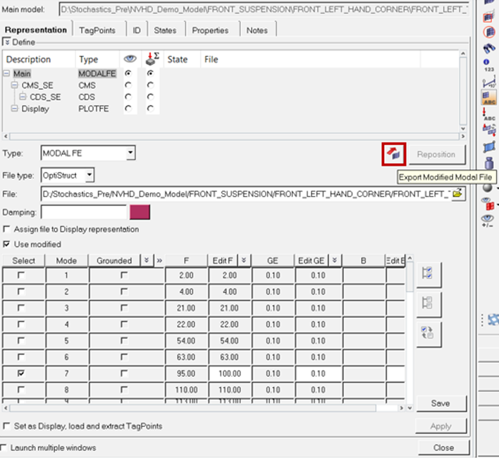
Figure 11.
Managing Tagpoints
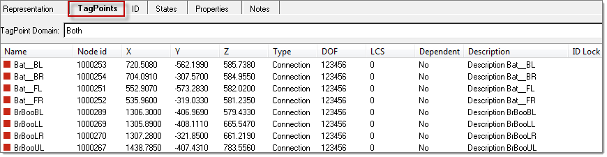
Figure 12.
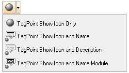
Figure 13.
- Lock ID
- Lock ID’s provide you with a means to maintain the ID’s of tagpoints without getting renumbered by locking them. This prevents accidental renumbering of tagpoints.
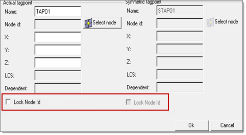
Figure 14. Locking ID's of Tagpoints as and When They are Created
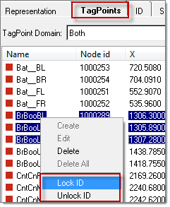
Figure 15. Locking ID's of Existing Tagpoints
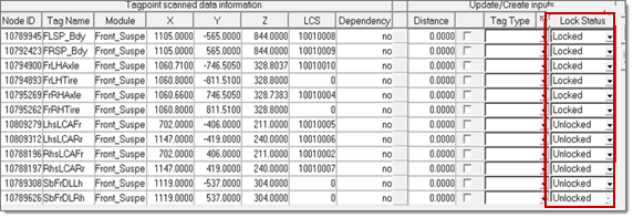
Figure 16. Locking ID's of Tagpoints Through the Tagpoint Mapping Tool
ID Tab
- Sub ranging
- Sub ranging provides you with a means to reserve a range so that it is not occupied and not referred by anybody. This is primarily needed if you want to reserve a certain ID range for a specific use and should not be occupied by other entities.
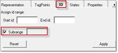
Figure 17.
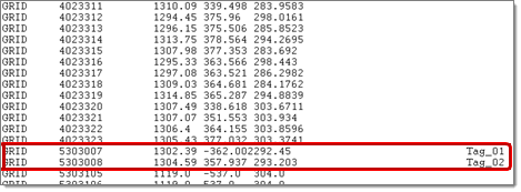
Figure 18. Front Stab Bar Without Sub Ranging
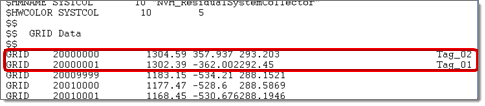
Figure 19. Front Stab Bar with Sub Ranging