Assign Thickness to Midsurface

Assign a thickness to shell elements that represent the middle surface of a solid part.

Geometric surfaces that represent the mid-plane of a part have thickness information stored in their definition if they are extracted using the midsurface function. Thickness data can be a single value for the entire part or a varying function.

The Midsurface Thickness Map script maps thickness data from surfaces to the associated nodes/elements via properties. You can also review the contour plot of thickness data with this script.

  1. From the menu bar, click Mesh > Assign > Midsurface Thickness.
    The Midsurface Thickness Map browser opens.
  2. For Assign thickness to, select which entities to assign thicknesses.
    • Choose Nodes, properties on elements to assigns\ the thickness values directly to the node cards, with a single property assigned to the selected elements. The nodes are found from all of the selected 2D elements.
    • Choose Nodes, properties on components to assign the thickness values directly to the node cards, with a single property assigned to the selected components. The nodes are found from all of the 2D elements in the selected components.
    • Choose Elements to assign the thickness and Z-offset values (where supported) directly to the element cards. For each solver interface, the values will be updated on the element card for that solver.
    • Choose Properties or elements to group elements that fall within user-specified thickness intervals into common ranges, then create and assign to each of those elements in each range a property with the range thickness value assigned to the property card image. Most solvers only have Z-offset defined on the element card, so this value will always be populated on the element cards for any solver that supports Z-offset. In order to execute this mode, a base property named t0 must be defined. The t0 property definition will be used for all created properties based on the option specified in the Organization Method section. This option performs the following generic steps:
      1. Create properties with name "t[thickness value]" by copying the properties of the base property t0 and assigning the appropriate thickness based on the value of the Organization Method.
      2. Assign to the elements that have thickness values within the specified ranges, based on the value of the Organization Method, the relevant property.
    • Choose Properties/Sections on components to group elements that fall within user-specified thickness intervals into common components, then create and assign to each of those components a property/section with the thickness value assigned to the property/section card image. Most solvers only have Z-offset defined on the element card, so this value will always be populated on the element cards for any solver that supports z-offset. In order to execute this mode, a base property/section must be assigned to a component named t0. The t0 component property/section will be used as the baseline for all newly created properties/sections based on the option specified in the Organization Method section. This option performs the following generic steps:
      1. Create components and properties with name "t[thickness value]" by copying the properties of the base property t0 and assigning the appropriate thickness based on the value of the Organization Method.
      2. Assign a property/section to its corresponding component.
      3. Remove any property assignments to the elements.
      4. Organize the elements that have thickness values within the specified ranges into the new components based on the value of the Organization Method.
    • Choose Organize only to create new components and sort the selected elements into them according to the Organization Method selected.
  3. To take z-offsets into account and assign z-offset values to the element cards for supported solvers, select the Use Z-offset values checkbox.
    HyperMesh uses z-offsets when midsurfacing parts that have variable thickness; the z-offset, which is saved as part of the midsurface data, tells a solver how much of a positive-normal offset exists between the actual part surface and the midsurface.
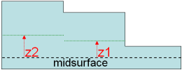

    Figure 1.
  4. For Thickness calculation method, select a method.
    • Choose Nodal values to calculate multiple thickness values for each element by finding the thickness at each of the element nodes. It is possible for a node to have multiple thickness values at a single location (shared surface edge where the surfaces have different thickness). The thickness calculated using that node for an element is dependent on which surface that element is associated to.
    • Choose Average to calculate a single thickness value for each element by averaging the thickness at each of the element nodes.
    • Choose Centroid to calculate a single thickness value for each element by calculating the thickness at the centroid of the element.
    • Choose Max to calculate a single thickness value for each element by calculating the thickness at each node of the element and taking the max value.
    • Choose Min to calculate a single thickness value is for each element by calculating the thickness at each node of the element and taking the min value.
  5. For Organization method, select an organization method to specify the thickness range intervals used to generate properties based on their thickness values.

    Based on the Assign thickness to option, the properties and components are generated for certain thickness ranges. Any element with a thickness value within that range is assigned that property or organized into that component.

    • Choose Gauge file to specify the thickness range intervals in a Gauge File.
    • Choose Range Interval to specify a thickness tolerance.
      Thickness range intervals are automatically generated based on the thickness tolerance using the following formula. The thickness assigned to each created component is n*tolerance.
      • Lower limit = (tolerance / 2) + (tolerance* i )
      • Upper limit = (tolerance / 2) + (tolerance* (i + 1))
      • Assigned value = tolerance*(i+1)
      • Where i = 0……n, n is determined by the maximum thickness in model divided by the user specified tolerance and then rounding to up to the next integer.
  6. Click Apply.
The thickness is assigned from the surface definition to the selected elements, based on the options specified.

Create a contour plot of the thicknesses on the selected elements/nodes based on the options specified by clicking Contour. This option does not assign the thickness to the nodes or elements; it is a review/display function only. It is very useful for visualizing and verifying the results of the utility before applying the Midsurface Thickness Map mapping operation.

If you choose Properties on elements, Properties on components, or Organize only under the Assign thickness to option, HyperMesh honors the Organization method settings during the contour process and the contour value is assigned based on that organization. This allows the contour to match with the applied results.

If you choose Elements or Properties on components for the Assign thickness to option, and choose to use Nodal values for the Thickness calculation method, the values may not exactly match the nodal values that are actually applied. There can be multiple thicknesses associated to a node if it shares an edge with multiple surfaces. Since HyperMesh can only provide one value for the contour, it always chooses the first value which might not match exactly with all of the applied values in these situations.