Elements
Elements are FE idealizations for a portion of a physical part.
Every element must be organized into one component, and therefore are mutually exclusive to a component.
Element Configurations
Each element has an associated element configuration. An element configuration tells HyperWorks how to draw, store, and work with the element.
Bar Elements
1D elements created in a space between two or three nodes of a model where beam properties are desired.
The nodes are related to each other based on the properties of the bar or beam element connecting them. Properties associated with bar elements include vector orientation, offset vectors that end at A and B, or at A, B, and C, and pin flags to tell it what degree of freedom should carry through the beam.
Bar elements are displayed as a line between two nodes with BAR2 or BAR3 written at the centroid of the element.
- Bar2
- Configuration 60 - 1D (1st order) elements with 2 nodes used to model axial, bending, and torsion behavior. Bar2 elements have a property reference, an orientation vector, offset vectors and ends A and B, and pin flags at ends A and B.
- Bar3
- Configuration 63 - 1D (2nd order) elements with 3 nodes used to model axial, bending, and torsion behavior. Bar3 elements have a property reference, an orientation vector, offset vectors and ends A and B, and pin flags at ends A and B.
Gap Elements
Configuration 70 - 1D elements created in a space between two nodes, or between a node and an element, of a model where contact may occur.
Create a gap element when you want to impose a nonlinear constraint on a model; this constraint will limit the amount of movement possible during analysis.
Gap elements have a property reference and an orientation vector.
Gap elements are displayed as a line between two nodes with GAP written at the centroid of the element.
Gap elements can translate to CGAP or CGAPG elements in OptiStruct, CGAP element in Nastran or *GAP option in Abaqus.
Hex Elements
3D hexahedra elements.
- Hex8
- Configuration 208 - 3D (1st order) hexahedra elements with 8 nodes.
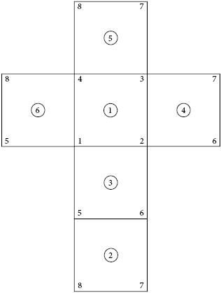
Figure 1. - Hex20
- Configuration 220 - 3D (2nd order) hexahedra elements with 20 nodes.
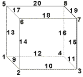
Figure 2. Element Configuration 220, 20-Noded Hexa
Joint Elements
Configuration 22 - 1D elements with 2, 4, or 6 nodes which have a property and orientation systems or nodes.
Joint element is a definition of a connection between two rigid bodies. Joint elements store a property and orientation information.
Joint elements are displayed with lines between the appropriate nodes and the letter J between nodes 1 and 3 of the element.
| Type | Type Name | Number of Nodes | Orientation | Solver Interface |
|---|---|---|---|---|
| 1 | Spherical joint | 2 |
|
|
| 2 | Revolute joint | 4 |
|
LS-DYNA |
| 3 | Cylindrical joint | 4 |
|
LS-DYNA |
| 4 | Planar joint | 4 |
|
LS-DYNA |
| 5 | Universal joint | 4 |
|
LS-DYNA |
| 6 | Translational joint | 6 |
|
LS-DYNA |
| 7 | Locking joint | 6 |
|
LS-DYNA |
| 8 | Ball joint | 2 | None | OptiStruct |
| 9 | Fixed joint | 2 | None | OptiStruct |
| 10 | Revolute joint | 2 |
|
OptiStruct |
| 11 | Translational1 joint | 2 |
|
OptiStruct |
| 12 | Cylindercal 1 joint | 2 |
|
OptiStruct |
| 13 | Universal joint | 2 |
|
OptiStruct |
| 14 | Constant_velocity joint | 2 |
|
OptiStruct |
| 15 | Planar joint | 2 |
|
OptiStruct |
| 16 | Inline joint | 2 |
|
OptiStruct |
| 17 | Perpendicular joint | 2 |
|
OptiStruct |
| 18 | Parallel axes joint | 2 |
|
OptiStruct |
| 19 | Inplane joint | 2 |
|
OptiStruct |
| 20 | Orient joint | 2 |
|
OptiStruct |
| 21 | Point_to_curve joint | 2 |
|
OptiStruct |
| 22 | Curve_to_curve joint | 2 |
|
OptiStruct |
| 23 | Point_to_deformable_curve joint | 2 |
|
OptiStruct |
| 24 | Point_to_deformable_surface joint | 2 |
|
OptiStruct |
| 25 | Translational_2N joint | 2 |
|
PAM-CRASH |
| 26 | Revolute_2N joint | 2 |
|
PAM-CRASH |
| 27 | Cylindrical_2N joint | 2 |
|
PAM-CRASH |
| 28 | Universal_2N joint | 2 |
|
PAM-CRASH |
| 29 | Flexion-Torsion joint | 2 |
|
PAM-CRASH |
| 30 | Planar_2N joint | 2 |
|
PAM-CRASH |
| 31 | General joint | 2 |
|
PAM-CRASH |
| 32 | Bracket joint | 2 |
|
PAM-CRASH |
| 33 | Free joint | 2 |
|
PAM-CRASH |
Mass Elements
Configuration 1 - 0D elements with a single node that allow you to assign concentrated mass to the model in order to represent a physical part that may not be modeled with another FE idealization.
Mass elements are displayed as a dot with the letter M written at the centroid of the element.
Master Elements
Master interface elements.
- Master3
- Configuration 123 - Master interface elements with 3 nodes. (Must be Type 1).
- Master4
- Configuration 124 - Master4 elements are master interface elements with 4 nodes. (Must be Type 1).
Penta Elements
3D triangular prism pentahedra elements.
- Penta6
- Configuration 206 - 3D (1st order) triangular prism pentahedra elements with 6
nodes.
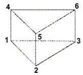
Figure 3. Element Configuration 206, 6-Noded Penta - Penta15
- Configuration 215 - 3D (2nd order) triangular prism pentahedra elements with 15
nodes.
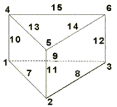
Figure 4. Element Configuration 215, 15-Noded Penta
Plot Elements
Configuration 2 - 1D elements with 2 nodes used for display purposes.
Plot elements are displayed as a line between two nodes.
Pyramid Elements
3D pyramid pentahedra elements.
- Pyramid5
- Configuration 205 - 3D (1st order) pyramid pentahedra elements with 5 nodes.
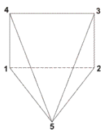
Figure 5. Element Configuration 205, 5-Noded Pyramid - Pyramid13
- Configuration 213 - 3D (2nd order) pyramid pentahedra elements with 5 nodes.
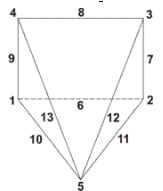
Figure 6. Element Configuration 213, 13-Noded Pyramid
Quad Elements
2D quadrilateral elements.
- Quad4
- Configuration 104 - 2D (1st order) quadrilateral elements with 4 nodes.

Figure 7. Element Configuration 104, 4-Noded Quad - Quad8
- Configuration 108 - 2D (2nd order) quadrilateral elements with 8 nodes.
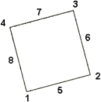
Figure 8. Element Configuration 108, 8-Noded Quad
RBE3 Elements
Configuration 56 - Rigid elements with one dependent node and variable independent nodes typically used to define the motion at the dependent node as a weighted average of the motions at the independent nodes.
Both the dependent node and independent nodes contain a coefficient (weighting factor) and user-defined degrees of freedom. The dependent degrees of freedom and weighting factors can be specified or automatically calculated based on the geometry.
RBE3 elements are displayed as lines between the dependent node and the independent node(s) with RBE3 displayed at the dependent node of the element.
Rigid Elements
Configuration 5 - Rigid 1D elements with 2 nodes used to model rigid connections.
Rigid elements are displayed as a line between two nodes with the letter R written at the centroid of the element.
Rigids can translate to RBE2 in Nastran or *MPC in Abaqus.
Rigidlink Elements
Configuration 55 - Rigid elements with one independent node and variable dependent nodes typically used to model rigid bodies.
Rigidlink elements have user-defined degrees of freedom which apply to all dependent nodes.
Rigidlink elements are displayed as lines between the independent node and the dependent node(s) with RL displayed at the independent node of the element.
Rod Elements
Configuration 61 - 1D elements with 2 nodes used to model axial behavior only.
The two nodes are related to each other based on the properties of the rod element connecting them. Rod elements have property pointers.
Rod elements are displayed as a line between two nodes with ROD written at the centroid of the element.
Rods can translate to CTUBES in Nastran or a C1D2 element in Abaqus.
Slave Elements
Slave interface elements.
- Slave1
- Configuration 135 - Slave interface elements with 1 node. (Must be Type 1).
- Slave3
- Configuration 133 - Slave interface elements with 3 node. (Must be Type 1).
- Slave4
- Configuration 134 - Slave interface elements with 1 node. (Must be Type 1).
Spring Elements
Configuration 21 - 1D elements used to model spring connections.
Spring elements have user-defined degrees of freedom, an orientation vector, and a property reference.
Spring elements are displayed as a line between two nodes with the letter K written at the centroid of the element.
- Spring
- 1D elements with 2 nodes used to model spring connections.
- Spring2N
- 1D elements with 2 nodes used to model spring connections.
- Spring3N
- 1D elements with 3 nodes used to model spring connections.
- Spring4N
- 1D elements with 4 nodes used to model spring connections.
Springs can translate to CELAS2 in Nastran or *SPRING in Abaqus.
Tetra Elements
3D tetrahedra elements.
- Tetra4
- Configuration 204 - 3D (1st order) tetrahedra elements with 4 nodes.
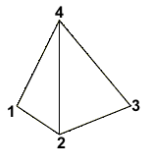
Figure 9. Element Configuration 204, 4-Noded Tetra - Tetra10
- Configuration 210 - 3D (2nd order) tetrahedra elements with 10 nodes.
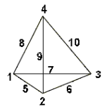
Figure 10. Element Configuration 210, 10-Noded Tetra
Tria Elements
2D triangular elements.
- Tria3
- Configuration 103 - 2D (1st order) triangular elements with 3 nodes.
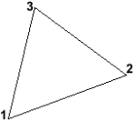
Figure 11. Element Configuration 103, 3-Noded Tria - Tria6
- Configuration 106 - 2D (2nd order) triangular elements with 6 nodes.
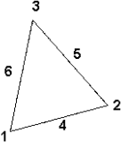
Figure 12. Element Configuration 106, 6-Noded Tria
Weld Elements
Configuration 3 - Rigid 1D elements with 2 nodes used to model welded connections.
Weld elements are displayed as a line between two nodes with the letter W written at the centroid of the element.
Xelems
1D multi-strand elements.
Supported Solver Cards
Solver cards supported for elements.
Abaqus Cards
| Card | Supported Element Configurations | Description |
|---|---|---|
| *COUPLING | Rigid/RBE3 | Define a surface-based coupling constraint where
the *SURFACE card points to elements. Note: The *COUPLING is also
supported as rigid elements (COUP_KIN) and RBE3 (COUP_DIS)
when *SURFACE points to nodes.
|
| *ELEMENT |
|
Defines elements by giving their nodes. |
| *ELGEN | Generates elements incrementally. These cards are resolved to individual entities on import and are written back on export the same way. Note: Standard 2D
only.
|
|
| *MPC | Rigid | Defines multi-point constraints. |
| *RELEASE |
|
Releases rotational degrees of freedom at one or
both ends of a beam element. For 2D problems, only dof6 (M1) is active. Add a *RELEASE card to this element by
clicking pins a = and pins b = and type in the Engineering Solutions dof code for the Abaqus release combination code you
want.
|
| AC1D2 | Bar2 | 2-node acoustic link |
| AC1D3 | Bar3 | 3-node acoustic link |
| AC2D3 | Tria3 | 3-node linear 2-D acoustic triangle |
| AC2D4 | Quad4 | 4-node linear 2-D acoustic quadrilateral |
| AC2D6 | Tria6 | 6-node quadratic 2-D acoustic triangular prism |
| AC2D8 | Quad8 | 8-node quadratic 2-D acoustic quadrilateral |
| AC3D10 | Tetra10 | 10-node quadratic acoustic tetrahedron |
| AC3D15 |
|
15-node quadratic acoustic triangular prism |
| AC3D20 |
|
20-node quadratic acoustic brick |
| AC3D4 | Tetra4 | 4-node linear acoustic tetrahedron |
| AC3D6 | Penta6 | 6-node linear acoustic triangular prism |
| AC3D8 | Hex8 | 8-node linear acoustic brick |
| AC3D8R | Hex8 | |
| ACAX3 | Tria3 | 3-node linear axisymmetric acoustic triangle |
| ACAX4 | Quad4 | 4-node linear axisymmetric acoustic quadrilateral |
| ACAX6 | Tria6 | 6-node quadratic axisymmetric acoustic triangle |
| ACAX8 | Quad8 | 8-node quadratic axisymmetric acoustic quadrilateral |
| ACIN3D3 | Tria3 | 3-node linear 3D acoustic infinite element |
| ACIN3D4 | Quad4 | 4-node linear 3D acoustic infinite element |
| ACIN3D6 | Tria6 | 6-node quadratic 3D acoustic infinite element |
| ACIN3D8 | Quad8 | 8-node quadratic 3D acoustic infinite element |
| B21 | Bar2 | 2-node linear beam in a plane |
| B21H | Bar2 | 2-node linear beam in a plane, hybrid formulation |
| B22 | Bar3 | 3-node quadratic beam in a plane |
| B22H | Bar3 | 3-node quadratic beam in a plane, hybrid formulation |
| B23 | Bar2 | 2-node cubic beam in a plane |
| B23H | Bar2 | 2-node cubic beam in a plane, hybrid formulation |
| B31 | Bar2 | 2-node linear beam |
| B31H | Bar2 | 2-node linear beam, hybrid formulation |
| B31OS | Bar2 | 2-node linear open-section beam |
| B31OSH | Bar2 | 2-node linear open-section beam, hybrid formulation |
| B32 | Bar3 | 3-node quadratic beam in space |
| B32 | Bar3 | 3-node quadratic beam |
| B32H | Bar3 | 3-node quadratic beam, hybrid formulation |
| B32OS | Bar3 | 3-node quadratic open-section beam |
| B32OSH | Bar3 | 3-node quadratic open-section beam, hybrid formulation |
| B33 | Bar2 | 2-node cubic beam |
| B33H | Bar2 | 2-node cubic beam, hybrid formulation |
| BEAM | Rigid | |
| C3D10 | Tetra10 | 10-node quadratic tetrahedron |
| C3D10E | Tetra10 | 10-node quadratic piezoelectric tetrahedron |
| C3D10H | Tetra10 | 10-node quadratic tetrahedron, hybrid, constant pressure |
| C3D10HS | Tetra10 | |
| C3D10I | Tetra10 | 10-node general-purpose quadratic tetrahedron, improved surface stress visualization |
| C3D10M | Tetra10 | 10-node modified tetrahedron, hourglass control |
| C3D10MH | Tetra10 | 10-node modified quadratic tetrahedron, hybrid, linear pressure, hourglass control |
| C3D10MP | Tetra10 | 10-node modified displacement and pore pressure tetrahedron, hourglass control |
| C3D10MPH | Tetra10 | 10-node modified displacement and pore pressure tetrahedron, hybrid, linear pressure, hourglass control |
| C3D10MT | Tetra10 | 10-node thermally coupled modified quadratic tetrahedron, hourglass control |
| C3D10S | ||
| C3D15 |
|
15-node quadratic triangular prism |
| C3D15E |
|
15-node quadratic piezoelectric triangular prism |
| C3D15H |
|
15-node quadratic triangular prism, hybrid, linear pressure |
| C3D20 |
|
20-node quadratic brick |
| C3D20E |
|
20-node quadratic piezoelectric brick |
| C3D20H |
|
20-node quadratic brick, hybrid, linear pressure |
| C3D20HT |
|
20-node thermally coupled brick, triquadratic displacement, trilinear temperature, hybrid, linear pressure |
| C3D20PH | Hex20 | 20-node brick, triquadratic displacement, trilinear pore pressure, hybrid, linear pressure |
| C3D20R |
|
20-node quadratic brick, reduced integration |
| C3D20RE |
|
20-node quadratic piezoelectric brick, reduced integration |
| C3D20RH |
|
20-node quadratic brick, hybrid, linear pressure, reduced integration |
| C3D20RHT |
|
20-node thermally coupled brick, triquadratic displacement, trilinear temperature, hybrid, linear pressure, reduced integration |
| C3D20RP | Hex20 | 20-node brick, triquadratic displacement, trilinear pore pressure, reduced integration |
| C3D20RPH | Hex20 | 20-node brick, triquadratic displacement, trilinear pore pressure, hybrid, linear pressure, reduced integration |
| C3D20RT |
|
20-node thermally coupled brick, triquadratic displacement, trilinear temperature, reduced integration |
| C3D20T |
|
20-node thermally coupled brick, triquadratic displacement, trilinear temperature |
| C3D30P | Hex20 | 20-node brick, triquadratic displacement, trilinear pore pressure |
| C3D4 | Tetra4 | 4-node linear tetrahedron |
| C3D4E | Tetra4 | 4-node linear piezoelectric tetrahedron |
| C3D4H | Tetra4 | 4-node linear tetrahedron, hybrid, linear pressure |
| C3D4P | Tetra4 | |
| C3D4T | Tetra4 | 4-node thermally coupled tetrahedron, linear displacement and temperature |
| C3D6 |
|
6-node linear triangular prism |
| C3D6E |
|
6-node linear piezoelectric triangular prism |
| C3D6H |
|
6-node linear triangular prism, hybrid, constant pressure |
| C3D6P | Penta6 | |
| C3D6T | Penta6 | 6-node thermally coupled triangular prism, linear displacement and temperature |
| C3D8 |
|
8-node linear brick |
| C3D8E |
|
8-node linear piezoelectric brick |
| C3D8H |
|
8-node linear brick, hybrid, constant pressure |
| C3D8HS | Hex8 | |
| C3D8HT |
|
8-node thermally coupled brick, trilinear displacement and temperature, hybrid, constant pressure |
| C3D8I |
|
8-node linear brick, incompatible modes |
| C3D8IH |
|
8-node linear brick, hybrid, linear pressure, incompatible modes |
| C3D8P | Hex8 | 8-node brick, trilinear displacement, trilinear pore pressure |
| C3D8PH | Hex8 | 8-node brick, trilinear displacement, trilinear pore pressure, hybrid, constant pressure |
| C3D8R |
|
8-node linear brick, reduced integration, hourglass control |
| C3D8RH |
|
8-node linear brick, hybrid, constant pressure, reduced integration, hourglass control |
| C3D8RHT |
|
8-node thermally coupled brick, trilinear displacement and temperature, reduced integration, hourglass control, hybrid, constant pressure |
| C3D8RHT | Pyramid5 | 8-node thermally coupled brick, trilinear displacement and temperature, reduced integration, hourglass control, hybrid, constant pressure |
| C3D8RP | Hex8 | 8-node brick, trilinear displacement, trilinear pore pressure, reduced integration |
| C3D8RPH | Hex8 | 8-node brick, trilinear displacement, trilinear pore pressure, reduced integration, hybrid, constant pressure |
| C3D8RT |
|
8-node thermally coupled brick, trilinear displacement and temperature, reduced integration, hourglass control |
| C3D8S | Hex8 | |
| C3D8T |
|
8-node thermally coupled brick, trilinear displacement and temperature |
| CAX3 | Tria3 | 3-node linear axisymmetric triangle |
| CAX3E | Tria3 | 3-node linear axisymmetric piezoelectric triangle |
| CAX3H | Tria3 | 3-node linear axisymmetric triangle, hybrid, constant pressure |
| CAX3T | Tria3 | 3-node axisymmetric thermally coupled triangle, linear displacement and temperature |
| CAX4 | Quad4 | 4-node bilinear axisymmetric quadrilateral |
| CAX4E | Quad4 | 4-node bilinear axisymmetric piezoelectric quadrilateral |
| CAX4H | Quad4 | 4-node bilinear axisymmetric quadrilateral, hybrid, constant pressure |
| CAX4HT | Quad4 | 4-node axisymmetric thermally coupled quadrilateral, bilinear displacement and temperature, hybrid, constant pressure |
| CAX4I | Quad4 | 4-node bilinear axisymmetric quadrilateral, incompatible modes |
| CAX4IH | Quad4 | 4-node bilinear axisymmetric quadrilateral, hybrid, linear pressure, incompatible modes |
| CAX4R |
|
4-node bilinear axisymmetric quadrilateral, reduced integration, hourglass control |
| CAX4RH | Quad4 | 4-node bilinear axisymmetric quadrilateral, hybrid, constant pressure, reduced integration, hourglass control |
| CAX4T | Quad4 | 4-node axisymmetric thermally coupled quadrilateral, bilinear displacement and temperature |
| CAX6 | Tria6 | 6-node quadratic axisymmetric triangle |
| CAX6H | Tria6 | 6-node quadratic axisymmetric triangle, hybrid, linear pressure |
| CAX6M | Tria6 | 6-node modified axisymmetric triangle, hourglass control |
| CAX6MH | Tria6 | 6-node modified quadratic axisymmetric triangle, hybrid, linear pressure, hourglass control |
| CAX8 | Quad8 | 8-node biquadratic axisymmetric quadrilateral |
| CAX8H | Quad8 | 8-node biquadratic axisymmetric quadrilateral, hybrid, linear pressure |
| CAX8HT | Quad8 | 8-node axisymmetric thermally coupled quadrilateral, biquadratic displacement, bilinear temperature, hybrid, linear pressure |
| CAX8R | Quad8 | 8-node biquadratic axisymmetric quadrilateral, reduced integration |
| CAX8RH | Quad8 | 8-node biquadratic axisymmetric quadrilateral, hybrid, linear pressure, reduced integration |
| CAX8RHT | Quad8 | 8-node axisymmetric thermally coupled quadrilateral, biquadratic displacement, bilinear temperature, hybrid, linear pressure, reduced integration |
| CAX8RT | Quad8 | 8-node axisymmetric thermally coupled quadrilateral, biquadratic displacement, bilinear temperature, reduced integration |
| CAX8T | Quad8 | 8-node axisymmetric thermally coupled quadrilateral, biquadratic displacement, bilinear temperature |
| CAXA41 | Quad4 | |
| CAXA4H1 | Quad4 | |
| CAXA4R1 | Quad4 | |
| CAXA4RH1 | Quad4 | |
| CAXA81 | Quad8 | |
| CAXA8H1 | Quad8 | |
| CAXA8P1 | Quad8 | |
| CAXA8R1 | Quad8 | |
| CAXA8R4 | Quad8 | |
| CAXA8RH1 | Quad8 | |
| CAXA8RH4 | Quad8 | |
| CAXA8RP1 | Quad8 | |
| CCL12 | Hex8 | 12-node cylindrical brick |
| CGAX3 | Tria3 | 3-node generalized linear axisymmetric triangle, twist |
| CGAX3H | Tria3 | 3-node generalized linear axisymmetric triangle, hybrid, constant pressure, twist |
| CGAX4 | Quad4 | 4-node generalized bilinear axisymmetric quadrilateral, twist |
| CGAX4H | Quad4 | 4-node generalized bilinear axisymmetric quadrilateral, hybrid, constant pressure, twist |
| CGAX4R | Quad4 | 4-node generalized bilinear axisymmetric quadrilateral, reduced integration, hourglass control, twist |
| CGAX4RH | Quad4 | 4-node generalized bilinear axisymmetric quadrilateral, hybrid, constant pressure, reduced integration, hourglass control, twist |
| CGAX6 | Tria6 | 6-node generalized quadratic axisymmetric triangle, twist |
| CGAX6H | Tria6 | 6-node generalized quadratic axisymmetric triangle, hybrid, linear pressure, twist |
| CGAX8 | Quad8 | 8-node generalized biquadratic axisymmetric quadrilateral, twist |
| CGAX8H | Quad8 | 8-node generalized biquadratic axisymmetric quadrilateral, hybrid, linear pressure, twist |
| CGAX8R | Quad8 | 8-node generalized biquadratic axisymmetric quadrilateral, reduced integration, twist |
| CGAX8RH | Quad8 | 8-node generalized biquadratic axisymmetric quadrilateral, hybrid, linear pressure, reduced integration, twist |
| CGAX8T | Quad8 | 8-node generalized axisymmetric thermally coupled quadrilateral, biquadratic displacement, bilinear temperature, twist |
| COH2D4 | Quad4 | 4-node two-dimensional cohesive element |
| COH3D6 | Penta6 | 6-node three-dimensional cohesive element |
| COH3D8 | Hex8 | 8-node three-dimensional cohesive element |
| COHAX4 | Quad4 | 4-node axisymmetric cohesive element |
| CONN2D2 |
|
Connector element in a plane between two nodes or ground and a node |
| CONN3D2 |
|
Connector element in space between two nodes or ground and a node |
| COUP_DIS | rbe3 | |
| COUP_KIN | Rigid | |
| CPE | Quad4 | |
| CPE3 | Tria3 | 3-node linear plane strain triangle |
| CPE3E | Tria3 | 3-node linear plane strain piezoelectric triangle |
| CPE3H | Tria3 | 3-node linear plane strain triangle, hybrid, constant pressure |
| CPE4E | Quad4 | 4-node bilinear plane strain piezoelectric quadrilateral |
| CPE4HT | Quad4 | 4-node plane strain thermally coupled quadrilateral, bilinear displacement and temperature, hybrid, constant pressure |
| CPE4I | Quad4 | 4-node bilinear plane strain quadrilateral, incompatible modes |
| CPE4IH | Quad4 | 4-node bilinear plane strain quadrilateral, hybrid, linear pressure, incompatible modes |
| CPE4P | Quad4 | 4-node plane strain quadrilateral, bilinear displacement, bilinear pore pressure |
| CPE4PH | Quad4 | 4-node plane strain quadrilateral, bilinear displacement, bilinear pore pressure, hybrid, constant pressure |
| CPE4R | Quad4 | 4-node bilinear plane strain quadrilateral, reduced integration, hourglass control |
| CPE4RH | Quad4 | 4-node bilinear plane strain quadrilateral, hybrid, constant pressure, reduced integration, hourglass control |
| CPE4RP | Quad4 | 4-node plane strain quadrilateral, bilinear displacement, bilinear pore pressure, reduced integration, hourglass control |
| CPE4RPH | Quad4 | 4-node plane strain quadrilateral, bilinear displacement, bilinear pore pressure, hybrid, constant pressure, reduced integration, hourglass control |
| CPE4T | Quad4 | 4-node plane strain thermally coupled quadrilateral, bilinear displacement and temperature |
| CPE6 | Tria6 | 6-node quadratic plane strain triangle |
| CPE6H | Tria6 | 6-node quadratic plane strain triangle, hybrid, linear pressure |
| CPE6M | Tria6 | 6-node modified quadratic plane strain triangle, hourglass control |
| CPE6MH | Tria6 | 6-node modified quadratic plane strain triangle, hybrid, linear pressure, hourglass control |
| CPE6MP | Tria6 | 6-node modified displacement and pore pressure plane strain triangle, hourglass control |
| CPE6MPH | Tria6 | 6-node modified displacement and pore pressure plane strain triangle, hybrid, linear pressure, hourglass control |
| CPE8 | Quad8 | 8-node biquadratic plane strain quadrilateral |
| CPE8H | Quad8 | 8-node biquadratic plane strain quadrilateral, hybrid, linear pressure |
| CPE8P | Quad8 | 8-node plane strain quadrilateral, biquadratic displacement, bilinear pore pressure |
| CPE8PH | Quad8 | 8-node plane strain quadrilateral, biquadratic displacement, bilinear pore pressure, hybrid, linear pressure stress |
| CPE8R | Quad8 | 8-node biquadratic plane strain quadrilateral, reduced integration |
| CPE8RH | Quad8 | 8-node biquadratic plane strain quadrilateral, hybrid, linear pressure, reduced integration |
| CPE8RP | Quad8 | 8-node plane strain quadrilateral, biquadratic displacement, bilinear pore pressure, reduced integration |
| CPE8RPH | Quad8 | 8-node biquadratic displacement, bilinear pore pressure, reduced integration, hybrid, linear pressure |
| CPEG3 | Tria3 | 3-node linear generalized plane strain triangle |
| CPEG4R | Quad4 | 4-node bilinear generalized plane strain quadrilateral, reduced integration, hourglass control |
| CPH4H | Quad4 | |
| CPS3 | Tria3 | 3-node linear plane stress triangle |
| CPS3E | 3-node linear plane stress piezoelectric triangle | |
| CPS4 | Quad4 | 4-node bilinear plane stress quadrilateral |
| CPS4E | Quad4 | 4-node bilinear plane stress piezoelectric quadrilateral |
| CPS4I | Quad4 | 4-node bilinear plane stress quadrilateral, incompatible modes |
| CPS4R | Quad4 | 4-node bilinear plane stress quadrilateral, reduced integration, hourglass control |
| CPS4T | Quad4 | 4-node plane stress thermally coupled quadrilateral, bilinear displacement and temperature |
| CPS6 | Tria6 | 6-node quadratic plane stress triangle |
| CPS6M | Tria6 | 6-node modified second-order plane stress triangle, hourglass control |
| CPS8 | Quad8 | 8-node biquadratic plane stress quadrilateral |
| CPS8R | Quad8 | 8-node biquadratic plane stress quadrilateral, reduced integration |
| DASHPOT1 | Mass | Dashpot between a node and ground, acting in a fixed direction |
| DASHPOT2 | Spring | Dashpot between two nodes, acting in a fixed direction |
| DASHPOTA | Spring | Axial dashpot between two nodes, whose line of action is the line joining the two nodes |
| DC1D2 | Bar2 | 2-node heat transfer link |
| DC1D3 | Bar3 | 3-node heat transfer link |
| DC2D3 | Tria3 | 3-node linear heat transfer triangle |
| DC2D3E | Tria3 | 3-node linear coupled thermal-electrical triangle |
| DC2D4 | Quad4 | 4-node linear heat transfer quadrilateral |
| DC2D4E | Quad4 | 4-node linear coupled thermal-electrical quadrilateral |
| DC2D6 | Tria6 | 6-node quadratic heat transfer triangle |
| DC2D6E | Tria6 | 6-node quadratic coupled thermal-electrical triangle |
| DC2D8 | Quad8 | 8-node quadratic heat transfer quadrilateral |
| DC2D8E | Quad8 | 8-node quadratic coupled thermal-electrical quadrilateral |
| DC3D10 | Tetra10 | 10-node quadratic heat transfer tetrahedron |
| DC3D10E | Tetra10 | 10-node quadratic coupled thermal-electrical tetrahedron |
| DC3D15 | Penta15 | 15-node quadratic heat transfer triangular prism |
| DC3D15E | Penta15 | 15-node quadratic coupled thermal-electrical triangular prism |
| DC3D20 | Hex20 | 20-node quadratic heat transfer brick |
| DC3D20E | Hex20 | 20-node quadratic coupled thermal-electrical brick |
| DC3D4 | Tetra4 | 4-node linear heat transfer tetrahedron |
| DC3D4E | Tetra4 | 4-node linear coupled thermal-electrical tetrahedron |
| DC3D6 | Penta6 | 6-node linear heat transfer triangular prism |
| DC3D6E | Penta6 | 6-node linear coupled thermal-electrical triangular prism |
| DC3D8 | Hex8 | 8-node linear heat transfer brick |
| DC3D8E | Hex8 | 8-node linear coupled thermal-electrical brick |
| DCAX3 | Tria3 | 3-node linear axisymmetric heat transfer triangle |
| DCAX3E | Tria3 | 3-node linear axisymmetric coupled thermal-electrical triangle |
| DCAX4 | Quad4 | 4-node linear axisymmetric heat transfer quadrilateral |
| DCAX4E | Quad4 | 4-node linear axisymmetric coupled thermal-electrical quadrilateral |
| DCAX6 | Tria6 | 6-node quadratic axisymmetric heat transfer triangle |
| DCAX6E | Tria6 | 6-node quadratic axisymmetric coupled thermal-electrical triangle |
| DCAX8 | Quad8 | 8-node quadratic axisymmetric heat transfer quadrilateral |
| DCAX8E | Quad8 | 8-node quadratic axisymmetric coupled thermal-electrical quadrilateral |
| DCC3D8 | Hex8 | 8-node convection/diffusion brick |
| DCC3D8D | Hex8 | 8-node convection/diffusion brick, dispersion control |
| DCCAX4 | Quad4 | 4-node axisymmetric convection/diffusion quadrilateral |
| DCCAX4D | Quad4 | 4-node axisymmetric convection/diffusion quadrilateral, dispersion control |
| DCOUP2D | rbe3 | Two-dimensional distributing coupling element |
| DCOUP3D | rbe3 | Three-dimensional distributing coupling element |
| DS3 | Tria3 | 3-node heat transfer triangular shell |
| DS4 | Quad4 | 4-node heat transfer quadrilateral shell |
| DS6 | Tria6 | 6-node heat transfer triangular shell |
| DS8 | Quad8 | 8-node heat transfer quadrilateral shell |
| EC3D8R | Hex8 | |
| EC3D8RT | Hex8 | |
| ELBOW31 | Bar2 | 2-node pipe in space with deforming section, linear interpolation along the pipe |
| ELBOW31B | Bar2 | 2-node pipe in space with ovalization only, axial gradients of ovalization neglected |
| ELBOW31C | Bar2 | 2-node pipe in space with ovalization only, axial gradients of ovalization neglected |
| ELBOW32 | Bar3 | 3-node pipe in space with deforming section, quadratic interpolation along the pipe |
| F2D2 | Bar2 | |
| F3D3 | Tria3 | 3-node linear 3-D triangular hydrostatic fluid element |
| F3D4 | Quad4 | 4-node linear 3-D quadrilateral hydrostatic fluid element |
| FAX2 | Bar2 | 2-node linear axisymmetric hydrostatic fluid element |
| FC3D4 | Tetra4 | |
| FC3D5 | Pyramid5 | |
| FC3D6 | Penta6 | |
| FC3D8 | Hex8 | |
| GAPCYL | Gap | Cylindrical gap between two nodes |
| GAPSPHER | Gap | Spherical gap between two nodes |
| GAPUNI | Gap | Unidirectional gap between two nodes |
| GK2D2 | Rod | 2-node two-dimensional gasket element |
| GK2D2N | Rod | 2-node two-dimensional gasket element with thickness-direction behavior only |
| GK3D12M | Penta6 | 12-node three-dimensional gasket element |
| GK3D12MN | Penta6 | 12-node three-dimensional gasket element with thickness-direction behavior only |
| GK3D18 | Hex8 | 18-node three-dimensional gasket element |
| GK3D18N | Hex8 | 18-node three-dimensional gasket element with thickness-direction behavior only |
| GK3D2 | Bar2 | 2-node three-dimensional gasket element |
| GK3D2N | Bar2 | 2-node three-dimensional gasket element with thickness-direction behavior only |
| GK3D4L | Quad4 | 4-node three-dimensional line gasket element |
| GK3D4LN | Quad4 | 4-node three-dimensional line gasket element with thickness-direction behavior only |
| GK3D6 | Penta6 | 6-node three-dimensional gasket element |
| GK3D6N | Penta6 | 6-node three-dimensional gasket element with thickness-direction behavior only |
| GK3D8 | Hex8 | 8-node three-dimensional gasket element |
| GK3D8N | Hex8 | 8-node three-dimensional gasket element with thickness-direction behavior only |
| GKPE4 | Quad4 | 4-node plane strain gasket element |
| GKPS4 | Quad4 | 4-node plane stress gasket element |
| GKPS4N | Quad4 | 4-node two-dimensional gasket element with thickness-direction behavior only |
| HMCONN | Mass | |
| ITS | ||
| ITSCYL | Rod | Cylindrical geometry tube support interaction element |
| ITSUNI | Rod | Unidirectional tube support interaction element |
| ITT21 | Mass | Tube-tube element for use with first-order, 2-D beam and pipe elements |
| ITT31 | Mass | Tube-tube element for use with first-order, 3-D beam and pipe elements |
| JOINTC | Spring | Three-dimensional joint interaction element |
| KINCOUP | Rigid | |
| LINK | Rigid | |
| M3D3 | Tria3 | 3-node triangular membrane |
| M3D4 | Quad4 | 4-node quadrilateral membrane |
| M3D4R | Quad4 | 4-node quadrilateral membrane, reduced integration, hourglass control |
| M3D6 | Tria6 | 6-node triangular membrane |
| M3D8 | Quad8 | 8-node quadrilateral membrane |
| M3D8R | Quad8 | 8-node quadrilateral membrane, reduced integration |
| MASS | Mass | Point mass |
| MGAX1 | Rod | 2-node linear axisymmetric membrane, twist |
| MGAX2 | Bar3 | 3-node quadratic axisymmetric membrane, twist |
| PC3D | Mass | |
| PIN | Rigid | |
| PIPE21 | Bar2 | 2-node linear pipe in a plane |
| PIPE21H | Bar2 | 2-node linear pipe in a plane, hybrid formulation |
| PIPE22 | Bar3 | 3-node quadratic pipe in a plane |
| PIPE22H | Bar3 | 3-node quadratic pipe in a plane, hybrid formulation |
| PIPE31 | Bar2 | 2-node linear pipe |
| PIPE31H | Bar2 | 2-node linear pipe in space, hybrid formulation |
| PIPE32 | Bar3 | 3-node quadratic pipe in space |
| PIPE32H | Bar3 | 3-node quadratic pipe in space, hybrid formulation |
| R2D2 | Rigid | |
| R3D3 | Tria3 | 3-node 3-D rigid triangular facet |
| R3D4 | Quad4 | 4-node 3-D bilinear rigid quadrilateral |
| RAX2 | Rigid | |
| RB2D2 | Rigid | |
| RB3D2 | Rigid | 2-node 3-D rigid beam |
| RDE |
|
2-node linear axisymmetric rigid link (for use in axisymmetric planar geometries) |
| ROTARYI | Mass | Rotary inertia at a point |
| S3 | Tria3 | 3-node triangular general-purpose shell, finite membrane strains |
| S3R | Tria3 | 3-node triangular general-purpose shell, finite membrane strains |
| S3RS | Tria3 | |
| S3RT | Tria3 | 3-node thermally coupled triangular general-purpose shell, finite membrane strains |
| S4 | Quad4 | 4-node general-purpose shell, finite membrane strains |
| S4R | Quad4 | 4-node general-purpose shell, reduced integration, hourglass control, finite membrane strains |
| S4R5 | Quad4 | 4-node thin shell, reduced integration, hourglass control, using five degrees of freedom per node |
| S4RS | Quad4 | |
| S4RSW | Quad4 | |
| S4RT | Quad4 | 4-node thermally coupled general-purpose shell, reduced integration, hourglass control, finite membrane strains |
| S4T | Quad4 | 4-node thermally coupled general-purpose shell, finite membrane strains |
| S8R | Quad8 | 8-node doubly curved thick shell, reduced integration |
| S8R5 | Quad8 | 8-node doubly curved thin shell, reduced integration, using five degrees of freedom per node |
| S8RT | Quad8 | 8-node thermally coupled quadrilateral general thick shell, biquadratic displacement, bilinear temperature in the shell surface |
| SAX1 | Bar2 | 2-node linear axisymmetric thin or thick shell |
| SAX2 | Bar3 | 3-node quadratic axisymmetric thin or thick shell |
| SC6R | Penta6 | 6-node triangular in-plane continuum shell wedge, general-purpose continuum shell, finite membrane strains |
| SC6RT | Penta6 | 6-node linear displacement and temperature, triangular in-plane continuum shell wedge, general-purpose continuum shell, finite membrane strains |
| SC8R | Hex8 | 8-node quadrilateral in-plane general-purpose continuum shell, reduced integration with hourglass control, finite membrane strains |
| SC8RT | Hex8 | 8-node linear displacement and temperature, quadrilateral in-plane general-purpose continuum shell, reduced integration with hourglass control, finite membrane strains |
| SFM3D3 | Tria3 | 3-node triangular surface element |
| SFM3D4 | Quad4 | 4-node quadrilateral surface element |
| SFM3D4R | Quad4 | 4-node quadrilateral surface element, reduced integration |
| SFM3D6 | Tria6 | 6-node triangular surface element |
| SFM3D8 | Quad8 | 8-node quadrilateral surface element |
| SFM3D8R | Quad8 | 8-node quadrilateral surface element, reduced integration |
| SFMAX1 | Rod | 2-node linear axisymmetric surface element |
| SFMAX2 | Bar3 | 3-node quadratic axisymmetric surface element |
| SFMGAX1 | Rod | 2-node linear axisymmetric surface element, twist |
| SFMGAX2 | Bar3 | 3-node quadratic axisymmetric surface element, twist |
| SPRING1 | Mass | Spring between a node and ground, acting in a fixed direction |
| SPRING2 | Spring | Spring between two nodes, acting in a fixed direction |
| SPRINGA | Spring | Axial spring between two nodes, whose line of action is the line joining the two nodes |
| STRI3 | Tria3 | 3-node triangular facet thin shell |
| STRI65 | Tria6 | 6-node triangular thin shell, using five degrees of freedom per node |
| T2D2 | Rod | 2-node linear 2-D truss |
| T2D2E | Rod | 2-node 2-D piezoelectric truss |
| T2D2H | Rod | 2-node linear 2-D truss, hybrid |
| T2D2T | Rod | 2-node 2-D thermally coupled truss |
| T2D3 | Rod | 3-node quadratic 2-D truss |
| T3D2 | Rod | 2-node linear 3D truss |
| T3D2E | Rod | 2-node 3D piezoelectric truss |
| T3D2H | Rod | 2-node linear 3D truss, hybrid |
| T3D2T | Rod | 2-node 3D thermally coupled truss |
| TIE | Rigid |
ANSYS Cards
| Card | Supported Element Configurations | Description |
|---|---|---|
| BEAM3 | Bar2 | 2D Elastic Beam Config 60, Type 2 |
| BEAM4 | Bar2 | 3D Elastic Beam Config 60, Type 1 |
| BEAM23 | Bar2 | 2D Plastic Beam Config 60, Type 9 |
| BEAM24 | Bar2 | 3D Thin-walled Beam Config 60, Type 6 |
| BEAM44 | Bar2 | 3D Elastic Tapered Unsymmetric Beam Config 60, Type 7 |
| BEAM54 | Bar2 | 2D Elastic Tapered Unsymmetric Beam Config 60, Type 10 |
| BEAM188 | Bar2 | 3D Linear Finite Strain Beam Config 60, Type 8 |
| BEAM189 | Bar3 | 3D Quadratic Finite Strain Beam Config 63, Type 1 |
| CERIG | Rigid | Ldof, Ldof2, Ldof3, Ldof4, Ldof5 Config 5, Type 1, 2 |
| CIRCU124 | Rod | General circuit element applicable to circuit simulation. |
| COMBIN14 | Spring | Spring-Damper Config 21, Type 1 |
| COMBIN39 | Spring | Nonlinear Spring Config 21, Type 2 |
| COMBIN40 | Spring | Combination Config 21, Type 3 |
| CONTA171 | Plot | 2D 2-Node Surface-to-Surface Contact Config 2, Type 3 |
| CONTA172 | Bar3 | 2D 3-Node Surface-to-Surface Contact Config 63, Type 12 |
| CONTA173 |
|
3D 4-Node Surface-to-Surface Contact
|
| CONTA174 |
|
3D 8-Node Surface-to-Surface Contact
|
| CONTA175 | Mass | 2D/3D Node-to-Surface Contact Config 1, Type 14 |
| CONTA177 |
|
3D Line-to-Surface Contact |
| CONTA178 | Gap | 3D Node-to-Node Contact Config 70, Type 3 |
| CONTAC12 | Gap | 2D Point-to-Point Contact Config 70, Type 2 |
| CONTAC48 | Tria3 | |
| CONTAC49 |
|
|
| CONTAC52 | Gap | 3D Point-to-Point Contact Config 70, Type 1 |
| CP | Rigid | Defines (or modifies) a set of coupled degrees of
freedom. Config 55, Type 1, 2 |
| CP_ELEC | Rigid | |
| CP_STRUC | Rigid | |
| CP_THERM | Rigid | |
| ELBOW290 | Bar3 | |
| FLUID29 |
|
2D Axisymmetric Harmonic Acoustic Fluid |
| FLUID30 |
|
3D Acoustic Fluid |
| FLUID80 | Hex8 | 3D Contained Fluid Config 208, Type 9 |
| FLUID116 | Rod | Coupled Thermal-Fluid Pipe Config 61, Type 12 |
| FLUID220 |
|
|
| FLUID221 | Tetra10 | |
| HF118 |
|
2D High-Frequency Quadrilateral Solid
|
| HF119 | Tetra10 | 3D High-Frequency Tetrahedral Solid Config 210, Type 11 |
| HF120 |
|
3D High-Frequency Brick Solid
|
| HYPER58 |
|
3D 8-Node Mixed u-P Hyperelastic Solid
|
| INFIN9 | Rod | |
| INFIN110 |
|
|
| INTER192 |
|
|
| INTER193 | Quad8 | |
| INTER194 |
|
|
| INTER195 |
|
|
| INTER205 |
|
|
| LINK1 | Rod | 2D Spar (or Truss) Config 61, Type 5 |
| LINK8 | Rod | 3D Spar (or Truss) Config 61, Type 1 |
| LINK10 | Rod | Tension-only or Compression-only Spar Config 61, Type 2 |
| LINK11 | Bar2 | Linear actuator Config 61, Type 25 |
| LINK31 | Rod | Radiation Link Config 61, Type 6 |
| LINK32 | Rod | 2D Conduction Bar Config 61, Type 7 |
| LINK33 | Rod | 3D Conduction Bar Config 61, Type 8 |
| LINK34 | Rod | Convection Link Config 61, Type 9 |
| LINK68 | Rod | Coupled Thermal-Electric Line Config 61, Type 14 |
| LINK180 | Rod | 3D Finite Strain Spar (or Truss) Config 61, Type 11 |
| MASS21 | Mass | Structural Mass Config 1, Type 1 |
| MASS71 | Mass | Thermal Mass Config 1, Type 2 |
| MESH200 |
|
Meshing Facet
|
| MPC184 | Rod | Multipoint Constraint Elements: Rigid Link, Rigid Beam,
Slider, Spherical, Revolute, Universal Config 61, Type 13 |
| PIPE16 | Bar2 | Elastic Straight Pipe Config 60, Type 3 |
| PIPE18 | Bar2 | Elastic Curved Pipe (Elbow) Config 60, Type 4 |
| PIPE20 | Rod | Plastic Straight Pipe Config 61, Type 4 |
| PIPE60 | Bar2 | Plastic Curved Pipe (Elbow) Config 60, Type 5 |
| PIPE288 | Bar2 | |
| PIPE289 | Bar3 | |
| PLANE2 | Tria6 | 2D 6-Node Triangular Structural Solid Config 106, Type 21 |
| PLANE13 |
|
2D Coupled-Field Solid
|
| PLANE25 |
|
Axisymmetric-Harmonic 4-Node Structural Solid
|
| PLANE35 | Tria6 | 2D 6-Node Triangular Thermal Solid Config 106, Type 7 |
| PLANE42 |
|
2D Structural Solid
|
| PLANE53 |
|
2D 8-Node Magnetic Solid
|
| PLANE55 |
|
2D Thermal Solid
|
| PLANE67 |
|
2D Coupled Thermal-Electric Solid
|
| PLANE75 |
|
Axisymmetric-Harmonic 4-Node Thermal Solid
|
| PLANE77 |
|
2D 8-Node Thermal Solid
|
| PLANE78 |
|
Axisymmetric-Harmonic 8-Node Thermal Solid
|
| PLANE82 |
|
2D 8-Node Structural Solid
|
| PLANE83 |
|
Axisymmetric-Harmonic 8-Node Structural Solid
|
| PLANE121 |
|
2D 8-Node Electrostatic Solid
|
| PLANE145 |
|
2D Quadrilateral Structural Solid p-Element
|
| PLANE146 | Tria6 | Config 106, Type 31 |
| PLANE162 |
|
Explicit 2D Structural Solid
|
| PLANE182 |
|
2D 4-Node Structural Solid
|
| PLANE183 |
|
2D 8-Node Structural Solid
|
| PLANE223 |
|
2D 8-Node Coupled-Field Solid |
| PRETS179 | Bar2 | Define a 2D or 3D pretension section within a meshed
structure. Config 60, Type 17 |
| RBE3 | RBE3 | Distributes the force/moment applied at the main node to a set of secondary nodes, taking into account the geometry of the secondary nodes as well as weighting factors. |
| SHELL28 | Quad4 | Shear/Twist Panel Config 104, Type 12 |
| SHELL41 |
|
Membrane Shell
|
| SHELL43 |
|
4-Node Plastic Large Strain Shell
|
| SHELL51 | Bar2 | Axisymmetric Structural Shell Config 60, Type 14 |
| SHELL57 |
|
Thermal Shell
|
| SHELL61 | Bar2 | Axisymmetric-Harmonic Structural Shell Config 60, Type 15 |
| SHELL63 |
|
Elastic Shell
|
| SHELL91 |
|
Nonlinear Layered Structural Shell
|
| SHELL93 |
|
8-Node Structural Shell
|
| SHELL99 |
|
Linear Layered Structural Shell
|
| SHELL131 |
|
4-Node Layered Thermal Shell
|
| SHELL132 |
|
8-Node Layered Thermal Shell
|
| SHELL143 |
|
4-Node Plastic Small Strain Shell
|
| SHELL150 |
|
8-Node Structural Shell p-Element
|
| SHELL157 |
|
Thermal-Electric Shell
|
| SHELL163 |
|
Explicit Thin Structural Shell
|
| SHELL181 |
|
4-Node Finite Strain Shell
|
| SHELL208 | Bar2 | 2-Node Finite Strain Axisymmetric Shell |
| SHELL209 | Bar2 | 3-Node Finite Strain Axisymmetric Shell |
| SHELL281 |
|
8-Node Finite Strain Shell |
| SOLID5 |
|
3D Coupled-Field Solid
|
| SOLID45 |
|
3D Structural Solid
|
| SOLID46 |
|
3D 8-Node Layered Structural Solid
|
| SOLID62 |
|
3D Magneto-Structural Solid
|
| SOLID64 |
|
3D Anisotropic Structural Solid
|
| SOLID69 |
|
3D Coupled Thermal-Electric Solid
|
| SOLID70 |
|
3D Thermal Solid
|
| SOLID72 | Tetra4 | |
| SOLID73 |
|
|
| SOLID87 | Tetra10 | 3D 10-Node Tetrahedral Thermal Solid Config 210, Type 5 |
| SOLID90 |
|
3D 20-Node Thermal Solid
|
| SOLID92 | Tetra10 | 3D 10-Node Tetrahedral Structural Solid Config 210, Type 3 |
| SOLID95 |
|
3D 20-Node Structural Solid
|
| SOLID96 |
|
3D Magnetic Scalar Solid
|
| SOLID97 |
|
3D Magnetic Solid
|
| SOLID98 | Tetra10 | Tetrahedral Coupled-Field Solid Config 210, Type 4 |
| SOLID117 |
|
3D 20-Node Magnetic Solid
|
| SOLID147 |
|
3D Brick Structural Solid p-Element |
| SOLID148 |
|
3D Tetrahedral Structural Solid p-Element
|
| SOLID164 |
|
Explicit 3D Structural Solid
|
| SOLID168 | Tetra10 | Explicit 3D 10-Node Tetrahedral Structural Solid |
| SOLID185 |
|
3D 8-Node Structural Solid
|
| SOLID186 |
|
3D 20-Node Structural Solid
|
| SOLID187 | Tetra10 | 3D 10-Node Tetrahedral Structural Solid Config 210, Type 6 |
| SOLID191 |
|
3D 20-Node Layered Structural Solid
|
| SOLID226 |
|
3D 20-Node Coupled-Field Solid |
| SOLID227 | Tetra10 | 3D 10-Node Coupled-Field Solid |
| SOLID236 |
|
3-D 20-Node element capable of modeling electromagnetic fields. The element has magnetic and electric degrees of freedom. |
| SOLID278 |
|
|
| SOLID279 |
|
|
| SOLID285 | Tetra4 | |
| SOLSH190 |
|
3D 8-Node Layered Solid Shell
|
| SURF151 | Bar2 | 2D Thermal Surface Effect Config 60, Type 12 |
| SURF152 |
|
3D Thermal Surface Effect
|
| SURF153 |
|
2D Structural Surface Effect
|
| SURF154 |
|
3D Structural Surface Effect
|
| SURF156 | Bar3 | 3D Structural Surface Line Load Effect |
| SURF251 | Rod | 2D Radiosity Surface Config 61, Type 25 |
| SURF252 |
|
3D Radiosity Surface
|
| TARGE169 |
|
2D Target Segment
|
| TARGE170 |
|
3D Target Segment
|
| VISCO88 |
|
2D 8-Node Viscoelastic Solid |
| VISCO107 |
|
3D 8-Node Viscoplastic Solid
|
EXODUS Cards
| Card | Supported Element Configurations | Description |
|---|---|---|
| BEAM | bar2 | |
| BEAM2 | bar2 | |
| BEAM3 | bar3 | |
| CIRCLE | mass | |
| HEX20 | hex20 | |
| HEX8 | hex8 | |
| PYRAMID13 | pyramid13 | |
| PYRAMID5 | pyramid5 | |
| QUAD4 | quad4 | |
| QUAD8 | quad8 | |
| RBAR | weld | |
| RJOINT | rigid | |
| RROD | rigid | |
| SHELL3 | tria3 | |
| SHELL4 | quad4 | |
| SHELL6 | tria6 | |
| SHELL8 | quad8 | |
| SPHERE | mass | |
| SPRING | spring | |
| TETRA10 | tetra10 | |
| TETRA4 | tetra4 | |
| TRI3 | tria3 | |
| TRI6 | tria6 | |
| TRIANGLE3 | tria3 | |
| TRIANGLE6 | tria6 | |
| TRUSS | rod | |
| WEDGE15 | penta15 | |
| WEDGE6 | penta6 |
LS-DYNA Cards
| Card | Supported Element Configurations | Description |
|---|---|---|
| *CONSTRAINED_GENERALIZED_WELD_BUTT_(ID) | Rigid | Define butt welds. Spot(default)/type 1, Fillet/type 2, and Butt/type 3 failure modes are supported. Failure information is based on weld type selected. Coordinate System ID can be selected. No Failure/Type 0 Card 36 entities are defined as *CONSTRAINED_NODAL_RIGID_BODIES in Keyword. They are a separate element type. |
| *CONSTRAINED_GENERALIZED_WELD_COMBINED_(ID) | Rigid | Define combined welds. |
| *CONSTRAINED_GENERALIZED_WELD_CROSS_FILLET_(ID) | Rigid | Define cross fillet welds. |
| *CONSTRAINED_GENERALIZED_WELD_FILLET_(ID) | Rigid | Define fillet welds. |
| *CONSTRAINED_GENERALIZED_WELD_SPOT_(ID) | Rigid | Define spot welds. |
| *CONSTRAINED_INTERPOLATION | RBE3 | Define an interpolation constrain. |
| *CONSTRAINED_JOINT_CONSTANT_VELOCITY | Joint | |
| *CONSTRAINED_JOINT_CYLINDRICAL | Joint | Define a joint between two rigid bodies. |
| *CONSTRAINED_JOINT_CYLINDRICAL_FAILURE(ID) | Joint | |
| *CONSTRAINED_JOINT_CYLINDRICAL_LOCAL(ID) | Joint | |
| *CONSTRAINED_JOINT_CYLINDRICAL_LOCAL_FAILURE(ID) | Joint | |
| *CONSTRAINED_JOINT_GEARS | Joint | |
| *CONSTRAINED_JOINT_LOCKING(ID) | Joint | |
| *CONSTRAINED_JOINT_LOCKING_FAILURE(ID) | Joint | |
| *CONSTRAINED_JOINT_LOCKING_LOCAL(ID) | Joint | |
| *CONSTRAINED_JOINT_LOCKING_LOCAL_FAILURE(ID) | Joint | |
| *CONSTRAINED_JOINT_PLANAR(ID) | Joint | |
| *CONSTRAINED_JOINT_PLANAR_FAILURE(ID) | Joint | |
| *CONSTRAINED_JOINT_PLANAR_LOCAL(ID) | Joint | |
| *CONSTRAINED_JOINT_PLANAR_FAILURE_LOCAL(ID) | Joint | |
| *CONSTRAINED_JOINT_PULLY | Joint | |
| *CONSTRAINED_JOINT_RACK_AND_PINION_ID | Joint | |
| *CONSTRAINED_JOINT_REVOLUTE | Joint | |
| *CONSTRAINED_JOINT_REVOLUTE_LOCAL(ID) | Joint | |
| *CONSTRAINED_JOINT_REVOLUTE_FAILURE(ID) | Joint | |
| *CONSTRAINED_JOINT_REVOLUTE_LOCAL_FAILURE(ID) | Joint | |
| *CONSTRAINED_JOINT_ROTATIONAL_MOTOR | Joint | |
| *CONSTRAINED_JOINT_SCREW | ||
| *CONSTRAINED_JOINT_SPHERICAL(ID) | Joint | |
| *CONSTRAINED_JOINT_SPHERICAL_LOCAL(ID) | Joint | |
| *CONSTRAINED_JOINT_SPHERICAL_FAILURE(ID) | Joint | |
| *CONSTRAINED_JOINT_SPHERICAL_LOCAL_FAILURE(ID) | Joint | |
| *CONSTRAINED_JOINT_STIFFNESS_TRANSLATIONAL | Joint | Define optional rotational and translational joint stiffness for joints defined by *CONSTRAINED_JOINT_OPTION. |
| *CONSTRAINED_JOINT_TRANSLATIONAL(ID) | Joint | |
| *CONSTRAINED_JOINT_TRANSLATIONAL_FAILURE(ID) | Joint | |
| *CONSTRAINED_JOINT_TRANSLATIONAL_LOCAL(ID) | Joint | |
| *CONSTRAINED_JOINT_TRANSLATIONAL_LOCAL_FAILURE(ID) | Joint | |
| *CONSTRAINED_JOINT_TRANSLATIONAL_MOTOR | Joint | |
| *CONSTRAINED_JOINT_UNIVERSAL(ID) | Joint | |
| *CONSTRAINED_JOINT_UNIVERSAL_FAILURE(ID) | Joint | |
| *CONSTRAINED_JOINT_UNIVERSAL_LOCAL(ID) | Joint | |
| *CONSTRAINED_JOINT_UNIVERSAL_LOCAL_FAILURE(ID) | Joint | |
| *CONSTRAINED_NODAL_RIGID_BODY | Rigid | Define a nodal rigid body. |
| *CONSTRAINED_NODAL_RIGID_BODY (2-Noded) | Rigid | |
| *CONSTRAINED_NODAL_RIGID_BODY_INERTIA | Rigid | Used when inertial properties are defined rather than computed. |
| *CONSTRAINED_NODAL_RIGID_BODY_INERTIA (2-Noded) | Rigid | |
| *CONSTRAINED_NODAL_RIGID_BODY_INERTIA _SPC | Rigid | |
| *CONSTRAINED_NODAL_RIGID_BODY_INERTIA _SPC (2-Noded) | Rigid | |
| *CONSTRAINED_NODAL_RIGID_BODY_SPC | Rigid | |
| *CONSTRAINED_NODAL_RIGID_BODY_SPC (2-Noded) | Rigid | |
| *CONSTRAINED_NODE_SET | Rigid | Define nodal constraint sets for translational motion in global coordinates. |
| *CONSTRAINED_NODE_SET (2-Noded) | Rigid | |
| *CONSTRAINED_NODE_SET_ID | Rigid | |
| *CONSTRAINED_RIVET | Weld | Define massless rivets between non-contiguous nodal pairs. |
| *CONSTRAINED_SHELL_TO_SOLID | Rigid | Define a tie between a shell edge and solid elements. |
| *CONSTRAINED_SPOTWELD_ID | Weld | Define massless spot welds between non-contiguous nodal
pairs. Normal and shear failure values can be edited. |
| *CONSTRAINED_SPOTWELD_FILTERED_FORCE_ID | Weld | |
| *ELEMENT_BEAM | Bar | Define two node elements including 3D beams, trusses, 2D
axisymmetric shells and 2D plane strain beam
elements. Thickness option can be added. This allows you to edit the parameters based on the element formulation in the property to which the beam points. |
| *ELEMENT_BEAM_OFFSET | Bar | |
| *ELEMENT_BEAM_OFFSET_PID | Bar | |
| *ELEMENT_BEAM_OFFSET_THICKNESS | Bar | |
| *ELEMENT_BEAM_ORIENTATION | Bar | |
| *ELEMENT_BEAM_PID | Bar | |
| *ELEMENT_BEAM_PID_ORIENTATION | Bar | |
| *ELEMENT_BEAM_PID_SCALAR | Bar | |
| *ELEMENT_BEAM_SCALAR | Bar | |
| *ELEMENT_BEAM_SCALAR_ORIENTATION | Bar | |
| *ELEMENT_BEAM_SECTION | Bar | |
| *ELEMENT_BEAM_SECTION_ORIENTATION | Bar | |
| *ELEMENT_BEAM_SECTION_PID | Bar | |
| *ELEMENT_BEAM_THICKNESS | Bar | |
| *ELEMENT_BEAM_THICKNESS_ORIENTATION | Bar | |
| *ELEMENT_BEAM_THICKNESS_PID | Bar | |
| *ELEMENT_BEAM_THICKNESS_SCALAR | Bar | |
| *ELEMENT_DISCRETE | Spring | Define a discrete (spring or damper) element between two
nodes or a node and ground. Scale factor, printing flags, and offset values can be edited. |
| *ELEMENT_INERTIA | Mass | Define a lumped inertia element assigned to a nodal point. |
| *ELEMENT_INERTIA_OFFSET | Mass | |
| *ELEMENT_MASS | Mass | Define a lumped mass element assigned to a nodal point or equally distributed to the nodes of a node set. |
| *ELEMENT_MASS_NODE_SET | Mass | Mass elements defined on node set |
| *ELEMENT_MASS_PART | Mass | Define additional non-structural mass to be distributed by an area weighted distribution to all nodes of a given part ID. |
| *ELEMENT_MASS_PART_SET | Mass | Mass elements defined on part set. |
| *ELEMENT_PLOTEL | Plot | Define a null beam element for visualization. |
| *ELEMENT_SEATBELT | Rod | Define a seat belt element. |
| *ELEMENT_SEATBELT_SENSOR | Sensors | Define seat belt sensor. |
| *ELEMENT_SHELL |
|
Define three, four, six and eight node elements including 3D
shells, membranes, 2D plane stress, plane strain, and
axisymmetric solids. Thickness and beta options can be added singularly or together. This allows you to edit the thickness and material angles to override the SECTION card. |
| *ELEMENT_SHELL_BETA |
|
|
| *ELEMENT_SHELL_BETA_OFFSET |
|
|
| *ELEMENT_SHELL_COMPOSITE |
|
|
| *ELEMENT_SHELL_DOF |
|
|
| *ELEMENT_SHELL_MCID |
|
|
| *ELEMENT_SHELL_MCID_OFFSET |
|
|
| *ELEMENT_SHELL_OFFSET |
|
|
| *ELEMENT_SHELL_THICKNESS |
|
|
| *ELEMENT_SHELL_THICKNESS_BETA |
|
|
| *ELEMENT_SHELL_THICKNESS_BETA_OFFSET |
|
|
| *ELEMENT_SHELL_THICKNESS_MCID |
|
|
| *ELEMENT_SHELL_THICKNESS_MCID_OFFSET |
|
|
| *ELEMENT_SHELL_THICKNESS_OFFSET |
|
|
| *ELEMENT_SOLID |
|
Define three-dimensional solid elements including 4 noded tetrahedrons and 8-noded hexahedrons. |
| *ELEMENT_SOLID_ORTHO |
|
Define a local coordinate system for orthotropic and anisotropic materials. |
| *ELEMENT_SOLID_TET4TOTET10 | Tetra4 | Converts 4 node tetrahedron solids to 10 node quadratic tetrahedron solids. |
| *ELEMENT_SPH | Mass | Define a lumped mass element assigned to a nodal point |
| *ELEMENT_TSHELL |
|
Define an eight node thick shell element which is available with either fully reduced or selectively reduced integration rules. |
| *INITIAL_MOMENTUM |
|
Defines initial momentum in the solid element at the start of
analysis. This momentum could be from previous analysis/step
carried forward to next analysis/step. This is supported as an attribute to an element to maintain its associativity with element inside HM. |
| *INITIAL_STRAIN_SHELL |
|
Defines stress in the shell element at the start of analysis.
This stress could be from previous analysis/step carried forward
to next analysis/step. This is supported as an attribute to an element to maintain its associativity with element inside HM. |
| *INITIAL_STRAIN_SOLID |
|
Defines stress in the solid element at the start of analysis.
This stress could be from previous analysis/step carried forward
to next analysis/step. This is supported as an attribute to an element to maintain its associativity with element inside HM. |
| *INITIAL_STRESS_BEAM | Bar | Defines stress in the beam element at the start of analysis.
This stress could be from previous analysis/step carried forward
to next analysis/step. This is supported as an attribute to an element to maintain its associativity with element inside HM. |
| *INITIAL_STRESS_SHELL |
|
Defines stress in the shell element at the start of analysis.
This stress could be from previous analysis/step carried forward
to next analysis/step. This is supported as an attribute to an element to maintain its associativity with element inside HM. |
| *INITIAL_STRESS_SOLID |
|
Defines stress in the solid element at the start of analysis.
This stress could be from previous analysis/step carried forward
to next analysis/step. This is supported as an attribute to an element to maintain its associativity with element inside HM. |
Nastran Cards
| Card | Supported Element Configurations | Description |
|---|---|---|
| CAABSF |
|
Defines a frequency-dependent acoustic absorber element in coupled fluid-structural analysis. |
| CACINF3 | Tria3 | Defines an acoustic conjugate infinite element with triangular base. |
| CACINF4 | Quad4 | Defines an acoustic conjugate infinite element with quadrilateral base. |
| CAERO1 | Quad4 | Defines an aerodynamic macro element (panel) in terms of two leading edge locations and side chords. This is used for Doublet-Lattice theory for subsonic aerodynamics and the ZONA51 theory for supersonic aerodynamics. |
| CAERO2 | Rod | Defines aerodynamic slender body and interference elements for Doublet-Lattice aerodynamics. |
| CBAR | Bar | Defines a simple beam element. |
| CBEAM | Bar | Defines a beam element. |
| CBEND | Bar | Defines a curved beam, curved pipe, or elbow element. |
| CBUSH |
|
Defines a generalized spring-and-damper structural element
that may be nonlinear or frequency dependent. Both elements with grounded terminals are supported. |
| CBUSH1D |
|
Defines the connectivity of a one-dimensional spring and
viscous damper element. Both elements with grounded terminals are supported. |
| CDAMP1 |
|
Defines a scalar damper element. Elements CDAMP1 and CDAMP2 with grounded terminals are not supported. |
| CDAMP2 |
|
Defines a scalar damper element without reference to a
material or property entry. Elements CDAMP1 and CDAMP2 with grounded terminals are not supported. |
| CDAMP3 |
|
Defines a scalar damper element that is connected only to
scalar points. Elements CDAMP1 and CDAMP2 with grounded terminals are not supported. |
| CDAMP4 |
|
Defines a scalar damper element that connected only to scalar
points and without reference to a material or property
entry. Elements CDAMP1 and CDAMP2 with grounded terminals are not supported. |
| CELAS1 |
|
Defines a scalar spring element. Elements CDAMP1 and CDAMP2 with grounded terminals are not supported. |
| CELAS2 |
|
Defines a scalar spring element without reference to a
property entry. Elements CDAMP1 and CDAMP2 with grounded terminals are not supported. |
| CELAS3 |
|
Defines a scalar spring element that connects only to scalar
points. Elements CDAMP1 and CDAMP2 with grounded terminals are not supported. |
| CELAS4 |
|
Defines a scalar spring element that is connected only to
scalar points, without reference to a property entry. Elements CDAMP1 and CDAMP2 with grounded terminals are not supported. |
| CFAST |
|
Defines a fastener with material orientation connecting two surface patches. |
| CGAP | Gap | Defines a gap or friction element. |
| CHACAB | Hex8 | Defines the acoustic absorber element in coupled fluid-structural analysis. |
| CHBDYE |
|
Defines a boundary condition surface element with reference
to a heat conduction element. This element is supported as GROUP. |
| CHBDYG |
|
Defines a boundary condition surface element without
reference to a property entry. This element is supported as GROUP. Creation from scratch is not yet supported. |
| CHBDYP |
|
Defines a boundary condition surface element with reference
to a PHBDY entry. CONVM is supported as a continuation card inside CHBDYP. |
| CHEXA (20-noded) | Hex20 | Defines a second order solid element, composed of 6
quadrilateral faces. In Nastran, you can define a second order element with missing mid-side nodes. Input data decks containing such elements are read by the translator as a first-order element. A message is written to the nastran.msg file indicating the corresponding element ID. |
| CHEXA (8-noded) | Hex8 | Defines a first order solid element, composed of 6 quadrilateral faces. |
| CMASS1 |
|
Defines a scalar mass element. |
| CMASS2 |
|
Defines a scalar mass element without reference to a property entry. |
| CMASS3 |
|
Defines a scalar mass element that is connected only to scalar points. |
| CMASS4 |
|
Defines a scalar mass element that is connected only to scalar points, without reference to a property entry. |
| CONM1 | Mass | Defines a 6 x 6 symmetric mass matrix at a geometric grid point. |
| CONM2 | Mass | Defines a concentrated mass at a grid point. |
| CONROD | Rod | Defines a rod element without reference to a property entry. |
| CPENTA (6-noded) | Penta6 | Defines the connections of a five-sided solid element with six to fifteen grid points. |
| CPENTA (15-noded) | Penta15 | Defines the connections of a five-sided solid element with
six to fifteen grid points. In Nastran, you can define a second order element with missing mid-side nodes. Input data decks containing such elements are read by the translator as a first-order element. A message is written to the nastran.msg file indicating the corresponding element ID. |
| CQUAD4 | Quad4 | Defines an isoparametric membrane-bending or plane strain quadrilateral plate element. |
| CQUAD8 | Quad8 | Defines a curved quadrilateral shell or plane strain element
with eight grid points. In Nastran, you can define a second order element with missing mid-side nodes. Input data decks containing such elements are read by the translator as a first-order element. A message is written to the nastran.msg file indicating the corresponding element ID. |
| CQUADR | Quad4 | Defines an isoparametric membrane and bending quadrilateral plate element. However, this element does not include membrane-bending coupling. This element is less sensitive to initial distortion and extreme values of Poisson’s ratio than the CQUAD4 element. It is a companion to the CTRIAR element. |
| CROD | Rod | Defines a tension-compression-torsion element. |
| CSHEAR | Quad4 | Defines a shear panel element. |
| CSEAM | Rod | |
| CTETRA (4-noded) | Tetra4 | Defines the connections of the four-sided solid element with four grid points. |
| CTETRA (10-noded) | Tetra10 | Defines the connections of the four-sided solid element with
ten grid points. In Nastran, you can define a second order element with missing mid-side nodes. Input data decks containing such elements are read by the translator as a first-order element. A message is written to the nastran.msg file indicating the corresponding element ID. |
| CTRIA3 | Tria3 | Defines an isoparametric membrane-bending or plane strain triangular plate element. |
| CTRIA6 | Tria6 | Defines a curved triangular shell element or plane strain
with six grid points. In Nastran, you can define a second order element with missing mid-side nodes. Input data decks containing such elements are read by the translator as a first-order element. A message is written to the nastran.msg file indicating the corresponding element ID. |
| CTRIAR | Tria3 | Defines an isoparametric membrane-bending triangular plate element. However, this element does not include membrane-bending coupling. It is a companion to the CQUADR element. |
| CTRIAX |
|
Defines an axisymmetric triangular element with up to 6 grid points for use in fully nonlinear (i.e., large strain and large rotations) hyperelastic analysis |
| CTRIAX6 |
|
Defines an isoparametric and axisymmetric triangular cross section ring element with midside grid points. |
| CTUBE | Rod | Defines a tension-compression-torsion tube element. |
| CQUADX |
|
Defines an axisymmetric quadrilateral element with up to nine
grid points for use in fully nonlinear (i.e. large strain and
large rotations) analysis or a linear harmonic or rotor dynamic
analysis. The element has between four and eight grid
points. Ninth grid selected in card edit of the element. |
| CVISC | Spring | Defines a viscous damper element. Elements CDAMP1 and CDAMP2 with grounded terminals are not supported. |
| CWELD |
|
Defines a weld or fastener connecting two surface patches or
points. Node-Node, Node-Patch, or Patch-Patch weld elements can be read. CWELD element is stored as an element of the rod configuration. CWELD elements using the ELEMID option not created in HyperMesh will be displayed as zero length. Currently, the Spotweld panel can only create Node-Node and Patch-Patch CWELD elements. HyperMesh always calculates the location of GA and GB by projecting GS in the normal direction of surface patch A and surface patch B, respectively. |
| GENEL | RBE3 | Defines a general element. |
| HM_SPRING | Spring | Defines a spring element, which is converted to Nastran entities on export, in a manner similar to that explained in Using HM_ELAS. |
| MBOLT | Mass | Defines a bolt for use in SOL 600 in countries outside the USA. |
| MBOLTUS | Mass | Defines a bolt for use only in SOL 600 and only in the USA. |
| PLOTEL | Plot | Defines a one-dimensional dummy element for use in plotting. |
| RBAR | Weld | Defines a rigid bar with six degrees-of-freedom at each
end. RBAR CNA field defaults to 123456. To edit the CNA, CNB, CMA, or CMB fields, you must view the card image for the RBAR element. |
| RBE2 |
|
Defines a rigid body with independent degrees-of-freedom that
are specified at a single grid point and with dependent
degrees-of-freedom that are specified at an arbitrary number of
grid points. An RBE2 element with one dependent node is identified as a rigid element, while an element with multiple dependent nodes is identified as a rigid link element. |
| RBE3 | RBE3 | Defines the motion at a reference grid point as the weighted
average of the motions at a set of other grid
points. Individual weight factors can be created on the independent nodes of RBE3 using the update functionality in the RBE3 panel. See the on-line help for the RBE3 panel for more information. |
| RJOINT | Defines a rigid joint element connecting two coinciding grid
points. RBE2 |
|
| RROD | Defines a rigid pin-ended element connection. |
OptiStruct Cards
| Card | Supported Element Configurations | Description |
|---|---|---|
| BMFACE |
|
Defines quad or tria faces that are in turn used to define a barrier to limit the total deformation for free-shape design regions. |
| CAABSF |
|
Defines the frequency-dependent fluid acoustic absorber element in coupled fluid-structural analysis. |
| CBAR | Bar2 | Defines a simple beam element (BAR) of the structural model. |
| CBEAM | Bar2 | Defines a beam element (BEAM) of the structural model. |
| CBUSH | Spring | Defines a generalized spring-damper structural element. |
| CBUSH1D |
|
Defines a one-dimensional spring-damper structural element. |
| CDAMP1 |
|
Defines a scalar damper element. Represented as a spring element type or as a mass element type (grounded CDAMP1). |
| CDAMP2 |
|
Defines a scalar damper element without reference to a
property entry. Represented as a spring element type or as a mass element type (grounded CDAMP2). |
| CDAMP3 |
|
Defines a scalar damper element that is connected only to
scalar points. Represented as a spring element type or as a mass element type (when a coordinate is constrained). |
| CDAMP4 |
|
Defines a scalar damper element that is connected only to
scalar points and is without reference to a material or property entry. Represented as a spring element type or as a mass element type (when a coordinate is constrained). |
| CELAS1 |
|
Defines a scalar spring element of the structural
model. Represented as a spring element type or as a mass element type (grounded CELAS1). |
| CELAS2 |
|
Defines a scalar spring element of the structural model
without reference to a property entry. Represented as a spring element type or as a mass element type (grounded CELAS2). Exported in large field format by optistructlf template. |
| CELAS3 |
|
Defines a scalar spring element that connects only to
scalar points. Represented as a spring element type or as a mass element type (when a coordinate is constrained). |
| CELAS4 |
|
Defines a scalar spring element that is connected only to
scalar points without reference to a property entry. Represented as a spring element type or as a mass element type (when a coordinate is constrained). |
| CFAST |
|
Define a fastener with material orientation connecting two
shell surfaces. Represented as a mass or rod element type, depending on fastener configuration. |
| CGAP | Gap | Defines a gap or friction element. The type of gap elements (either CGAP or CGAPG) is automatically determined based on whether the element is node-to-node or node-to-elem. |
| CGAPG |
|
Defines a node-to-obstacle gap element. The obstacle may be
an element face or a patch of nodes. The type of gap elements (either CGAP or CGAPG) is automatically determined based on whether the element is node-to-node or node-to-elem. |
| CGASK6 | Penta6 | Defining the connections of the GASK6 solid gasket element. |
| CGASK8 | Hex8 | Defining the connections of the GASK8 solid gasket element. |
| CGASK12 | Penta15 | Defining the connections of the GASK12 solid gasket element. |
| CGASK16 | Hex20 | Defining the connections of the GASK16 solid gasket element. |
| CHACAB | Hex8 | Defines the acoustic absorber element in coupled fluid-structural analysis. |
| CHBDYE | Slave1 | Defines a surface element for application of thermal
boundary condition. Defined using the Interfacespanel with the CONDUCTION or CONVECTION type. |
| CHEXA (8-noded) | Hex8 | Defines a first order solid element, composed of 6 quadrilateral faces. |
| CHEXA (20-noded) | Hex20 | Defines a second order solid element, composed of 6
quadrilateral faces. A second order element with missing mid-side nodes can be defined in OptiStruct. Input data decks containing such elements are read by the translator as a first-order element. A message is written to the OptiStruct.msg file indicating the corresponding element ID. |
| CMASS1 |
|
Defines a scalar mass element. Represented as a spring element type or as a mass element type (grounded CMASS1). |
| CMASS2 |
|
Defines a scalar mass element without reference to a
property entry. Represented as a spring element type or as a mass element type (grounded CMASS2). |
| CMASS3 |
|
Defines a scalar mass element that is connected only to
scalar points. Represented as a spring element type or as a mass element type (when a coordinate is constrained). |
| CMASS4 |
|
Defines a scalar mass element that is connected only to
scalar points, without reference to a property entry. Represented as a spring element type or as a mass element type (when a coordinate is constrained). |
| CMBEAM | Bar2 | Defines a beam element for multibody dynamics solution sequence without reference to a property entry. |
| CMBUSH | Spring | Defines a bushing element without reference to a property entry. |
| CMBUSHC | Spring | |
| CMBUSHE | Spring | |
| CMBUSHT | Spring | |
| CMSPDP | Spring | Defines a spring damper element without reference to a property entry for multibody solution sequence. |
| CMSPDPC | Spring | Defines a spring damper element without reference to a property entry for multibody solution sequence. |
| CMSPDPE | Spring | Defines a spring damper element without reference to a property entry for multibody solution sequence. |
| CMSPDPT | Spring | Defines a spring damper element without reference to a property entry for multibody solution sequence. |
| CONM1 | Mass | Defines a 6x6 mass matrix at a geometric grid point. |
| CONM2 | Mass | Defines a concentrated mass at a grid point of the
structural model. Exported in large field format by optistructlf template. |
| CONROD | Rod | Defines a rod element without reference to a property entry. |
| CONV | Slave1 | Defines a free convection boundary condition for heat
transfer analysis through connection to a surface element (CHBDYE
card). Represented as a continuation to CHBDYE secondary element card. |
| CPENTA (6-noded) | Penta6 | Defines a first order solid element, composed of 3 quadrilateral and 2 triangular faces. |
| CPENTA (15-noded) | Penta15 | Defines a second order solid element, composed of 3
quadrilateral and 2 triangular faces.
A second order element with missing mid-side nodes can be defined in OptiStruct. Input data decks containing such elements are read by the translator as a first-order element. A message is written to the OptiStruct.msg file indicating the corresponding element ID. |
| CPYRA (5-noded) | Pyramid5 | Defines a first order solid element, composed of 1 quadrilateral and 4 triangular faces. |
| CPYRA (13-noded) | Pyramid13 | Defines a second order solid element, composed of 1
quadrilateral and 4 triangular faces. A second order element with missing mid-side nodes can be defined in OptiStruct. Input data decks containing such elements are read by the translator as a first-order element. A message is written to the OptiStruct.msg file indicating the corresponding element ID. |
| CQUADR | Quad4 | Equivalent to CQUAD4. Unlike other Nastran codes, a 6 degree-of-freedom per node formulation is used for all shell elements. |
| CQUAD4 | Quad4 | Defines a quadrilateral plate element (QUAD4) of the structural model. This element uses a 6 degree-of-freedom per node formulation. |
| CQUAD8 | Quad8 | Defines a curved quadrilateral shell element with eight grid points. |
| CROD | Rod | Defines a tension-compression-torsion element (ROD) of the structural model. |
| CSHEAR | Quad4 | Defines a shear panel element. |
| CTAXI | Tria3 | Defines an axisymmetric triangular cross-section ring element for use in linear analysis. |
| CTETRA (4-noded) | Tetra4 | Defines a first order solid element, composed of 4 triangular faces. |
| CTETRA (10-noded) | Tetra10 | Defines a second order solid element, composed of 4
triangular faces. A second order element with missing mid-side nodes can be defined in OptiStruct. Input data decks containing such elements are read by the translator as a first-order element. A message is written to the OptiStruct.msg file indicating the corresponding element ID. |
| CTRIAR | Tria3 | CTRIAR entry is equivalent to CTRIA3. Unlike other Nastran codes, a 6 degrees-of-freedom per node formulation is used for all shell elements. |
| CTRIAX6 | Tria6 | Defines an axisymmetric triangular cross-section ring element for use in Linear Analysis. |
| CTRIA3 | Tria3 | Defines a triangular plate element (TRIA3) of the structural model. This element uses a 6 degree-of-freedom per node formulation. |
| CTRIA6 | Tria6 | Defines a curved triangular shell element with six grid points. |
| CTUBE | Rod | Defines a tension-compression-torsion element (TUBE) of the structural model. |
| CVISC | Spring | Defines a viscous damper element. Represented as a spring element type. |
| CWELD |
|
Defines a weld or fastener connecting two surface patches
or points. Represented as a rod element type. |
| DHEXA8 | Hex8 | |
| DQUAD4 | Quad4 | |
| DPENTA6 | ||
| DTETRAA4 | Tetra4 | |
| DTRIA3 | Tria3 | |
| HMSPRING | Spring | Defines a spring element, which is converted to OptiStruct entities on export, in a manner similar to that explained in Using HM_ELAS. |
| JOINT | Joint | Defines a joint. |
| PLOTEL | Plot | Defines a one-dimensional dummy element for use in plotting. |
| PLOTEL3 |
|
Defines a three-noded, two-dimensional dummy element for use in plotting. |
| PLOTEL4 |
|
Defines a four-noded, two-dimensional dummy element for use in plotting. |
| QBDY1 | Flux | Defines a uniform heat flux for CHBDYE elements. |
| RBAR | Weld | Defines a rigid bar with six degrees-of-freedom at each end. |
| RBE2 |
|
Defines a rigid body whose independent degrees-of-freedom
are specified at a single grid point and whose dependent degrees-of-freedom are
specified at an arbitrary number of grid points. An RBE2 element with one dependent node is represented as a rigid element type, while an element with multiple dependent nodes is represented as a rigid link element type. |
| RBE3 | Rbe3 | Defines the motion at a "reference" grid point as the weighted average of the motions at a set of other grid points. |
| RROD | Rod | Defines a pin-ended rod that is rigid in extension. |
PAM-CRASH Cards
The component of the element refers to a material, which contains the material definition for PAM-CRASH.
| Card | Supported Element Configurations | Description |
|---|---|---|
| ASSOCIATE | Rigids | Defines entities to be converted from deformable to rigid. |
| BAR / | Rod | Bar element. |
| BASE_BODY | Rigid | Rigid bodies on which the boundary conditions are defined, used in Multibody systems. |
| BEAM / | Bar2 | Beam element. If the orientation vector is defined via vectors, the string VECTOR is displayed in the N3 field, and a zero is written in the exported deck. If the y-direction node is directly specified, its ID is displayed in the N3 field. |
| BSHEL / | Hex8 | 8-noded brick shell element. |
| EDG | Rod | |
| ELINK / | Rod | Link element. The element must be edited in the card previewer to define the connections. |
| JOINT / | Rod | Joint element. The element must be edited in the card previewer to define element orientation. |
| KJOIN / | Rod | Kinematic joint element. The element must be edited in the card previewer to define element orientation. |
| LLINK / | Rod | Link element. The element must be edited in the card previewer to define the connections. |
| MASS | Mass | Added mass. |
| MEMBR / |
|
Membrane element. |
| MTJOIN / | FE Joint | Multiple node to one node Kinematic joint element. |
| MTOCO / | Rigid | Rigid element. |
| NODCO / | Rigid | Nodal constraint definition. This configuration allows you to create nodal constraints via entity sets. The element must be edited in the card previewer. Degrees of freedom are ignored. |
| OTMCO / | RBE3 | One node to multiple node constraints. |
| PLINK / | Mass | Plink element. The element must be edited in the card
previewer. Mass value is ignored. Use the following
templates to handle the welds:
|
| PLINK_VI | Rod | These elements are created during connector realization to show the actual connections. They are not exported. |
| RETRA / | Mass | The element must be edited in the card previewer. Mass value is ignored. |
| RBODY / | Weld | Rigid body with 2 nodes. When created, the default value for rigid body type is 1. |
| RBODY / | Rigid | This configuration allows you to create rigid bodies via entity sets. The element must be edited in the card previewer. Degrees of freedom are ignored. |
| SEG |
|
The elements are used in entity selection. With this keyword, only nodes of these elements are output along with SEG keyword. |
| SENPT / | Mass | |
| SHELL / | Mass | Shell element. Mass value is ignored. Mass defined with a keyword other than NOD is not supported. The reader creates one mass element for each NOD definition in the MASS card, therefore the exported deck will contain the same number of MASS/cards as many NOD definitions. |
| SHELL / | Tria3 | The default behavior for tria3 elements is Coo
triangles. To output standard triangles (N3 = N4). |
| SHELL / | Quad4 | |
| SLINK / |
|
The element must be edited in the card previewer to define the connections. |
| SLIPR / | Mass | The element must be edited in the card previewer. Mass value is ignored. |
| SOLID / |
|
8-noded brick element. |
| SPH / | Mass | |
| SPRING / | Spring | Spring element. The element must be edited in the card previewer to define element orientation. |
| SPRGBM / | Spring | Spring beam element. The element must be edited in the card previewer to define element orientation. |
| TETRA / | Tetra10 | 10-noded tetra element. Local frame definition. |
| TETR4 / | Tetra4 | 4-noded tetra element. |
| TSHEL / | Quad4 | 4-noded thick shell element. The element must be edited in the card previewer to define the connections. |
Permas Cards
| Card | Supported Element Configurations | Description |
|---|---|---|
| BEAM2 | Bar2 | 2 noded straight general beam |
| BECOC | Bar2 | 2 noded straight thin-walled tube |
| BECOP | Bar2 | 2 noded straight thin-walled tube |
| BECOS | Bar2 | 2 noded straight solid beam |
| BETAC | Bar2 | 2 noded straight tapered thin-walled tube |
| BETOP | Bar2 | 2 noded straight thin-walled open beam |
| CA1ZERF3 | Spring | Zero Force Element with 1 Node and Three Translational Stiffnesses |
| CA2ZERF1 | Spring | Translational Zero Force Element with 2 Nodes |
| CA2ZERF3 | Spring | Zero Force Element with 2 Nodes and Three Translational Stiffnesses |
| CONAX2 | Bar2 | |
| CONAX3 | Bar3 | |
| CONA3 | Tria3 | 3 noded triangular surface convection and radiation element. |
| CONA4 | Quad4 | 4 noded quadrilateral surface convection and radiation element. |
| CONA6 | Tria6 | 6 noded triangular surface convection and radiation element. |
| CONA8 | Quad8 | 8 noded quadrilateral surface convection and radiation element. |
| CONS3 | Tria3 | 3 noded triangular shell surface convection and radiation element. |
| CONS4 | Quad4 | 4 noded quadrilateral shell surface convection and radiation element. |
| CONS6 | Tria6 | 6 noded triangular shell surface convection and radiation element. |
| CONS8 | Quad8 | 8 noded quadrilateral shell surface convection and radiation element. |
| DAMP1 | Spring | Translational viscous damper. |
| DAMP3 | Spring | Viscous damper for three degrees of freedom. |
| DAMP6 | Spring | Viscous damper for six degrees of freedom. |
| FLA2 | Rod | 2 noded straight flange (rod). |
| FLA3 | Bar3 | 3 noded straight flange (rod). |
| FLHEX8 | Hex8 | 8 noded fluid hexahedron. |
| FLHEX20 | Hex20 | 20 noded fluid hexahedron. |
| FLPENT6 | Penta6 | 6 noded fluid pentahedron. |
| FLPENT15 | Penta15 | 15 noded fluid pentahedron. |
| FLPYR5 | Pyramid5 | 5 noded fluid pyramid. |
| FLTET4 | Tetra4 | 4 noded fluid tetrahedron. |
| FLTET10 | Tetra10 | 10 noded fluid tetrahedron. |
| FSINTA3 | Tria3 | 3 noded triangular fluid structure interface element. |
| FSINTA4 | Quad4 | 4 noded quadrilateral fluid structure interface element. |
| FSINTA6 | Tria6 | 6 noded triangular fluid structure interface element. |
| FSINTA8 | Quad8 | 8 noded quadrilateral fluid structure interface element. |
| GKHEX8 | Hex8 | 8 noded solid hexahedron. |
| GKHEX20 | Hex20 | 20 noded solid hexahedron. |
| GKPNT6 | Penta6 | 6 noded solid pentahedron. |
| GKPNT15 | Penta15 | 15 noded solid pentahedron. |
| HEXE8 | Hex8 | 8 noded solid hexahedron. |
| HEXE20 | Hex20 | 20 noded solid hexahedron. |
| LOADA3 | Tria3 | 3 node triangular load carrying membrane element. |
| LOADA4 | Quad4 | 4 node quadrilateral load carrying membrane element. |
| LOADA6 | Tria6 | 6 node triangular load carrying membrane element. |
| LOADA8 | Quad8 | 8 node quadrilateral load carrying membrane element. |
| MASS3 | Mass | Point mass. |
| MASS6 | Mass | Rigid mass. |
| $MPC ASSIGN | Rigid | Dependent nodes are forced to have the same displacement as an independent node. User can specify degrees of freedom for dependent and independent nodes. |
| $MPC JOIN | Rigid | Pairwise identical displacements. |
| $MPC RIGID | Rigid | Rigid regions. |
| $MPC SAME | Rigid | Identical corresponding displacements. |
| $MPC WLSCON | RBE3 | Weighted averaged connection. |
| MPC_IQUAD4 | RBE3 |
Quadrilateral Interpolation Surface |
| MPC_IQUAD8 | RBE3 |
Quadrilateral Interpolation Surface |
| MPC_IQUAD9 | RBE3 |
Quadrilateral Interpolation Surface |
| MPC_ITRIA3 | RBE3 |
Triangular Interpolation Surface |
| MPC_ITRIA6 | RBE3 |
Triangular Interpolation Surface |
| NLDAMP | Spring | Nonlinear translational viscous damper. |
| NLDAMPR | Spring | Nonlinear rotational viscous damper. |
| NLSTIFF | Spring | Nonlinear translational spring. |
| NLSTIFFR | Spring | Nonlinear rotational spring. |
| PENTA6 | Penta6 | 6 noded solid pentahedron. |
| PENTA15 | Penta15 | 15 noded solid pentahedron. |
| PLOTA3 | Tria3 | 3 noded triangular plot element. |
| PLOTA4 | Quad4 | 4 noded quadrilateral plot element. |
| PLOTA6 | Tria6 | 6 noded triangular plot element. |
| PLOTA8 | Quad8 | 8 noded quadrilateral plot element. |
| PLOTL2 | Plot | 2 noded straight line plot element. |
| PLOTL3 | Bar3 | 3 noded straight line plot element. |
| PYRA5 | Pyramid5 | 5 noded solid pyramid. |
| QUAD4 | Quad4 | 4 noded quadrilateral shell element. |
| QUAD4S | Quad4 | |
| QUAM4 | Quad4 | 4 noded quadrilateral plane membrane element. |
| QUAM8 | Quad8 | 8 noded quadrilateral plane membrane element |
| QUAMS4 | Quad4 | 4 noded quadrilateral solid shell element |
| QUAMS8 | Quad8 | 8 noded quadrilateral solid shell element |
| QUAX4 | Quad4 | 4 noded quadrilateral axisymmetric solid element |
| QUAX8 | Quad8 | 8 noded quadrilateral axisymmetric solid element |
| SHEAR4 | Quad4 | 4 noded quadrilateral plane shear panel element. |
| SHELL3 | Tria3 | 3 noded triangular shell element for laminates. |
| SHELL4 | Quad4 | 4 noded quadrilateral shell element for laminates. |
| SPRINGX1 | Spring | |
| SPRINGX2 | Spring | |
| SPRINGX3 | Spring | |
| SPRING1 | Spring | Translational spring. |
| SPRING3 | Spring | Spring with three translational stiffnesses |
| SPRING6 | Spring | Spring with three translational and three rotational stiffnesses. |
| TET4 | Tetra4 | 4 noded solid tetrahedron. |
| TET10 | Tetra10 | 10 noded solid tetrahedron. |
| TRIA3 | Tria3 | 3 noded triangular shell element. |
| TRIA3K | Tria3 | 3 noded triangular thin shell element. |
| TRIA3S | Tria3 |
Axisymmetric Solid Element, 3 Noded Triangular Sandwich Shell Element |
| TRIAX3 | Tria3 |
Axisymmetric Solid Element |
| TRIAX6 | Tria6 |
Axisymmetric Solid Element |
| TRIM3 | Tria3 | 3 noded triangular plane membrane element. |
| TRIM6 | Tria6 | 6 noded triangular plane membrane element. |
| TRIMS3 | Tria3 | 3 noded triangular solid shell element |
| TRIMS6 | Tria6 | 6 noded triangular solid shell element. |
| X1DAMP3 | Mass | Scalar viscous damper at one node with three degrees of freedom. |
| X1DAMP6 | Mass | Scalar viscous damper at one node with six degrees of freedom. |
| X1GEN6 | Mass | General element at one node with six degrees of freedom. |
| X1MASS3 | Mass | Scalar mass at two nodes with three degrees of freedom. |
| X1MASS6 | Mass | Scalar mass at one node with six degrees of freedom. |
| X1STIFF3 | Mass | Scalar spring at one node with three degrees of freedom. |
| X1STIFF6 | Mass | Scalar spring at one node with six degrees of freedom. |
| X2DAMP3 | Spring | Scalar viscous damper at two nodes with three degrees of freedom. |
| X2DAMP6 | Spring | Scalar viscous damper at two nodes with six degrees of freedom. |
| X2GEN6 | Mass | General element at two nodes with six degrees of freedom. |
| X2STIFF3 | Spring | Scalar spring at two nodes with three degrees of freedom. |
| X2STIFF6 | Spring | Scalar spring at two nodes with six degrees of freedom. |
Radioss Cards
- Shell thickness is included with the connectivity data. The default value is contained in the property set.
- The time history is provided for the elements.
- 3D elements are supported.
- Degenerated 3D solid elements (from Hexa), such as Tetra and Penta, are included with the present 3D elements.
| Card | Supported Element Configurations | Description |
|---|---|---|
| /ADMAS | Mass | Assign additional non-structural mass to nodes or a group of nodes. Optionally the total additional non-structural mass of a part or a group of parts can be defined (applied to shells and solids only) or a surface mass can be assigned to a surface and Radioss would then compute the added node based mass value using area (volume) - weighted distribution. |
| /BEAM | Bar | Describes the beam elements. Two properties (/PROP/TYPE3 (BEAM) and /PROP/TYPE18 (INT_BEAM)) are available for this beam element. The properties describing a beam element are all defined in a local beam coordinate system. |
| /BRIC20 | Hex20 | Describes 3D solid elements (20 Node Brick Elements). This quadratic element should be used with the property /PROP/SOLID. |
| /BRICK |
|
Defines a hexahedral solid element and thick shell element with 8 nodes. |
| /CYL_JOINT | Rigid | Defines cylindrical joints. |
| /QUAD | Quad4 | Describes the 2D solid elements. QUAD elements must be defined in the global YZ plane. |
| /RBE2 | Rigid | Defines a rigid body whose independent degrees of freedom are specified at a single main node and whose dependent degrees of freedom are specified at an arbitrary number of secondary nodes. |
| /RBE3 | RBE3 | Defines the motion of a reference (secondary) node as the weighted average of the motions of sets of main nodes. |
| /RBODY | Rigid | Defines rigid bodies. |
| /RLINK | Rigid | Defines a rigid link. The rigid link imposes the same velocity on all the secondary nodes in one or more directions. |
| /SHELL | Quad4 | Describes input for 4-node shell elements. |
| /SH3N | Tria3 | Describes the triangular 3-node shell elements. |
| /SPHCEL | Mass | Describes the SPH cells. |
| /SPRING2N | Spring2N | Describes the 2-noded spring elements. |
| /SPRING3N | Spring3N | Describes the 3-noded spring elements. |
| /SRPING4N | Spring4N | Describes the 4-noded spring elements. |
| /TETRA4 | Tetra4 | Describes a tetrahedral solid element with 4 nodes. |
| /TETRA10 | Tetra10 | Describes a tetrahedral solid element with 10 nodes. |
| /TRUSS | Rod | Describes one dimension truss elements, which could be used with property /PROP/TYPE2 (TRUSS). Truss could only carry axial load (like for bar). |
| /XELEM | Xelem | Describes the multi-strand elements. |
Samcef Cards
| Card | Supported Element Configurations | Description |
|---|---|---|
| AXISYM |
|
|
| BUSH | Spring | |
| COMP AXISYM |
|
|
| COMP DEFO PLAN |
|
|
| COMP MEMB BIDIM |
|
|
| COMP PLAN GENE |
|
|
| COMP VOLU |
|
|
| COMP VOLU COQUE |
|
|
| COQU DEFO PLAN |
|
|
| DEFO GENE |
|
|
| DEFO PLAN |
|
|
| FLUX THERMIQUE |
|
|
| FOUR MULT HARM |
|
|
| FOURIER |
|
|
| HETEROSIS |
|
|
| HYBR VOLU |
|
|
| HYBRID VOLU COQUE |
|
|
| MEMB AXISYM | Bar2 | |
| MEMB BIDIM |
|
|
| MEMB FLEXION |
|
|
| MEMB FOURIER | Bar2 | |
| MEMB MULT HARM | Bar2 | |
| MINDLIN |
|
|
| RBE3 | RBE3 | |
| SAND VOLU |
|
|
| SOLID SHELL |
|
|
| THER AXISYM |
|
|
| THER COQU |
|
|
| THERMIQU |
|
|
| TUYAU | Rod | |
| TUYAU THERMIQUE | Rod | |
| VOLU COQUE |
|
|
| VOLUMIC |
|