Cross Sections
Cross section entities store cross section definitions used in a crash analysis.
A cross section is defined by a set of nodes and elements. These sets can be explicitly defined in the entity or computed by intersecting a given geometry (plane, circle) with a set of elements or components.
Supported Solver Cards
Solver cards supported for cross sections.
LS-DYNA Cards
| Card | Description |
|---|---|
| *DATABASE_CROSS_SECTION_PLANE(ID) | XsectionPlane |
| *DATABASE_CROSS_SECTION_SET(ID) | Define a cross section for resultant forces written to an ASCII file SECFORC. |
PAM-CRASH 2G
| Card | Description |
|---|---|
| SECFO / | |
| SECFO / NTYP = PLANE |
Transmission force at cutting plane Graphics available. |
| SECFO / NTYP = CONTACT |
Cumulated contact forces No graphics available. |
| SECFO / NTYP = LINK |
Cumulated link forces No graphics available. |
| SECFO / NTYP = SECTION |
Transmission force at section No graphics available. |
| SECFO / NTYP = SUPPORT |
Support reaction force No graphics available. |
| SECFO / NTYP = VOLFRAC |
Fraction of volume affected by a defined criterion No graphics available. |
| SECFO / NTYP = CONT_MS |
Contact forces between Main and Secondary nodal groups No graphics available. |
| SECFO / NTYP = DETECT |
Accumulated nodal mass in selected volume No graphics available. |
| SECFO / NTYPE = TIED_MS |
Tied forces between main and secondary nodal groups (v2018) |
Radioss Cards
| Card | Description |
|---|---|
| /SECT | A section is a set of nodes and a set of
elements. Note: Block Format
Keyword
|
| /SECT/CIRCLE | A section is a set of nodes and a set of elements.
Sets are built automatically, by intersecting the concerned groups of elements with
a disc. Note: Block Format
Keyword
|
| /SECT/PARAL | A section is a set of nodes and a set of elements.
Sets are built automatically, by intersecting the concerned groups of elements with
a parallelogram. Note: Block Format
Keyword
|
Create Cross Sections
Create cross sections using the Cross Section Assistant.
-
If you are creating a single cross section:
-
In the Base Node field, define the location of the cross section.
Manually enter the coordinates of the cross section, or click
 select the base node in the
graphics area.
select the base node in the
graphics area. -
In the Normal Direction field, define the normal of the cutting plane
to be used for the generation of the cross section.
Manually enter the coordinates of the vector, or click to pick two or three
nodes.
-
In the Base Node field, define the location of the cross section.
 Figure 1. Radioss Cross Section |
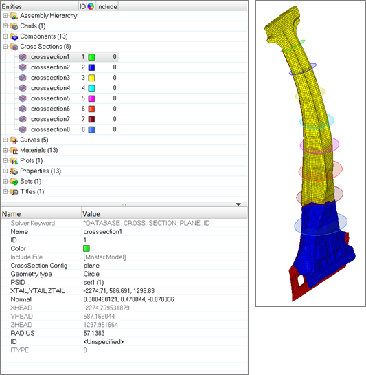 Figure 2. LS-DYNA Cross Section |