This realization creates a continuous or discontinuous hexa weld
with a predefined pattern.
Restriction: Available in Abaqus, Nastran, OptiStruct, and PAM-CRASH 2G.
For Abaqus, this realization uses the
prop_abaqus_acm.tcl property script. For Nastran and OptiStruct,
prop_nastran_acm.tcl is used.
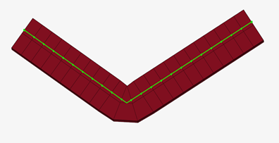
All defined information is stored on the connector, and can be exported into the
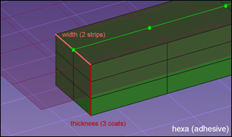
connector .xml file. Figure 1. Seam Hexa Adhesives
Seam Hexas are created from the Seam panel.
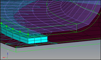
The HEXA elements will be centered about the seam connector if the seam connector is not
close to a free edge. If the distance between the seam connector and free edge of a
component is less than half the width of the HEXA, then the realization of HEXA elements
will start from the seam connector and will be extruded in the direction away from the
edge. Figure 2.
For OptiStruct and Nastran
solvers, the HEXA elements are tied to a shell using RBE3s at locations where the HEXA
nodes and shell nodes are non-coincident. If the HEXA nodes and shell nodes are
coincident then RBE2s will be used to tie them.
This realization type is intended to work on meshes, both shells and solids.
The hexa dimension depends on the following settings:
The length of a hexa is predefined by the distribution of the test points along
the seam connector. This is defined by spacing or density during the connector
creation.
The width of the single hexa depends on the number of strips and the defined
total width of the seam, which is measured perpendicular to the seam
direction.
The thickness of a single hexa depends on the number of defined coats and the
selected thickness option.
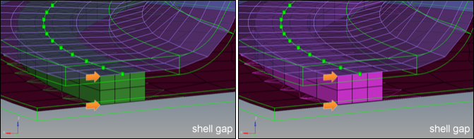
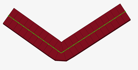
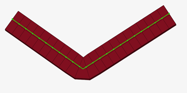
The available thickness options interact with the consider shell thickness option and
offset for hexa positioning option. In the figures below, the green seams on the left
take into account the thickness as well as the shell offset. This information is used
for dimensioning and positioning the hexas. For the pink seams on the right side, the
hexas are always positioned around the exact middle between the current shell positions.
The shell thicknesses are taken into account only for the hexa height, but not for the
positioning. The orange lines and arrows in the figures below illustrate the
dependencies for the positioning.
shell gap
The seam completely and exactly fills the gap between the two shells. Shell
thicknesses and offsets are not considered. Figure 3.
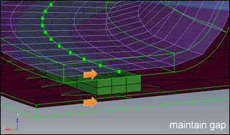
maintain gap
The seam is positioned in the exact middle between the shells. The seam
thickness is adjusted, that on both sides the gap between shell and seam
fits the defined gap size. Shell thicknesses and offsets are not
considered. Figure 4.
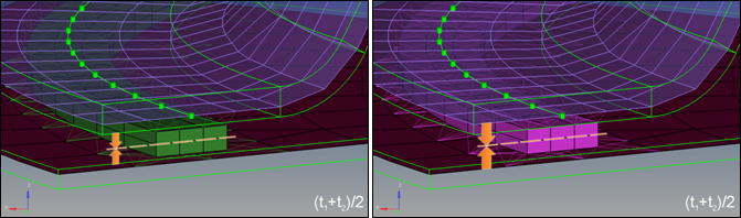
(t1+t2)/2
The seam thickness is calculated by averaging both shell thicknesses. On the
left side the offsets and thicknesses are taken into account, so that the
seam is positioned around the middle of the air gap. On the right side the
seam is just positioned around the middle of the shell positions. Figure 5.
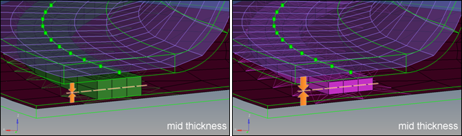
midthickness
On the left side the exact air gap is determined and filled with the seam.
On the right side the seam thickness is calculated by subtracting half the
thickness of both shells from the total distance of the shells. Figure 6.
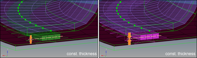
const. thickness
The thickness of the seam is predefined for both; on the left side the seam
is positioned around the middle of the air gap, on the right side around the
middle of the two shells. Figure 7.
The following options are available for Hexa Position:
Anything with "edge"
Snapping to edge activated when using any of the hexa position options that
refer to an “edge”. This is to ensure that the connector can identify an
“edge” to realize to.
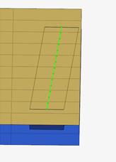
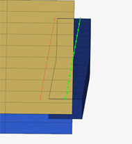
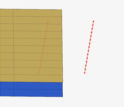
Midpoint to connector
The connector realization will follow the connector line until the connector
line is in space (Figure 8). At which point it will try to realize at the closest
projections within tolerance (Figure 9). Once the connector is outside of the tolerance it will
fail (Figure 10).
Figure 8.
Figure 9.
Figure 10.
The following options are available for Adjust Width:
This parameter will try to limit the self-intersection of the connector and creation of
poor quality hexa elements around sharp corners.
None
Allows the hexa to self-intersect.
Figure 11.
Reduce Width
Reduces the inner width to find a position where the mesh is not
intersecting.
Figure 12.
Move Hexa
Performs the same operation as the previous option by reducing the inner
width to find a position where the mesh is not intersecting. This will then
add the removed width back to the outer diameter to maintain the specified
width.