Stiffened Panel Mesh
Create a quad dominant mapped mesh from orthogonal lines for global FE model creation. Bar/beam mesh will be created around the edges. This is mainly used for the fuselage section.
Note: It is desired to have orthogonal lines.
Restriction: Only available in Nastran and
OptiStruct solvers in the Aerospace user
profile.
From the menu bar, click .
Use this tool to:
- Create mapped quad mesh using orthogonal lines
- Create quad surface regions automatically using line boundary
- Create structured mesh on those regions with user-specified element density
- Offset the nodes and element IDs
- Use existing manifold surfaces, if present, to trim those lines
Review Description
| Option | Description | Result |
|---|---|---|
| Curve List A | Select a set of lines that are parallel. | Selected lines will be highlighted. |
| Curve List B | Select a set of lines that are perpendicular to curve list A. | Selected lines will be highlighted. |
| Boundary Curve U | Select a single line from curve list A which represents the U direction for the meshing region. The lowest element/node numbers will lie on this line. | Selected line will be highlighted. |
| Boundary Curve V | Select a single line from curve list B which represents the V direction for the meshing region. The lowest element/node numbers will lie on this line and the intersection of boundary curve U. | Element and node numbering will start at the intersection of boundary curve U and V. |
| Manifold Surface | Select the surfaces on which curve list A and B could be projected within the given tolerance. | The nodes will be created on the surface. |
| Respect the Manifold surface | Select this toggle | The nodes will be placed on this surface. |
| Delete the Auxiliary geometry | Select this toggle | The sub region (surface) created between the intersecting lines will be deleted after the meshing operations. |
| Global Model Tolerance | Provide a suitable tolerance within which all the curves will intersect. | Lines will be intersected to create a rectangular meshing region. |
| Destination Component Name | Provide the name of the component where the resulting mesh will reside. | A new component will be created, and the mesh will be moved to that component, if the new component toggle is selected. |
| Starting element ID | Provide an ID that is greater than the max element ID in the model. | Element ID will start from the ID given at the corner of the boundary curve (UV) intersection. It will increase in the U direction first. |
| Starting Node ID | Provide an ID that is greater than the max node ID in the model. | Node ID will start from the ID given at the corner of the boundary curve (UV) intersection. It will increase in the U direction first. |
| Elements in U | Number of elements in each bay in the U direction. | In each bay in the U direction elements will be created with the number specified. |
| Elements in V | Number of elements in each bay in the V direction. | In each bay in the V direction elements will be created with the number specified. |
Expected Results
In this example, quad dominant mesh will be created. Matching 1D (beam) elements will also be created around the bay boundary along the original lines. Element and node IDs will start from the offset IDs provided.
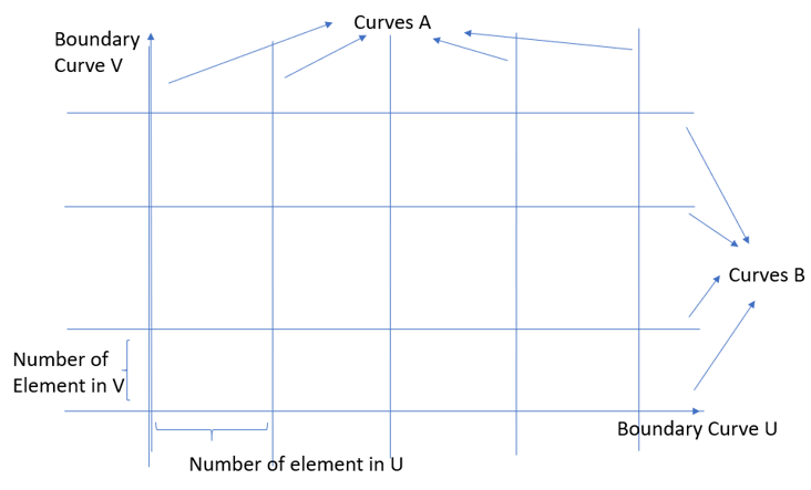
Figure 1. Input for the Stiffened Panel Mesh
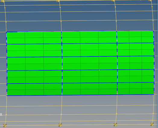
Figure 2. Mapped Mesh Created
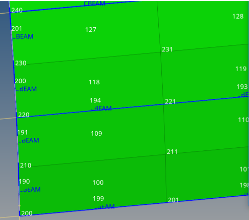
Figure 3. . Beams are created with correct node ID (200) and element ID (100) offset