Connectors and E-Line Management Tutorial
This section of the tutorial will walk you through the steps of review and realizing E-Lines.
Realizing E-Lines
-
Using standard Windows multi select option (Holding Ctrl key and selecting
Elines from the table), click Realize

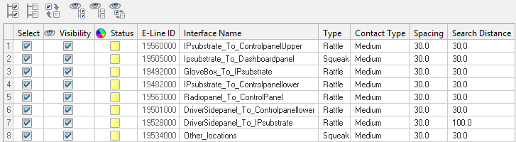
Figure 1.Once all the lines are realized, you can view the message log for information.
-
Once the realization completes, you can see the status has changed from
Yellow to Green
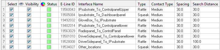
Figure 2. -
Select any line from the list and click Visibility buttons at the top of the
table to view the lines.
The selected line will be isolated in graphics area.
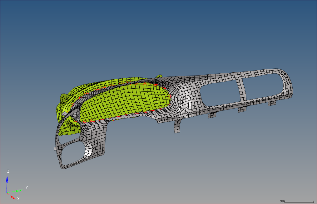
Figure 3. -
Click navigation buttons
 or
or  beside Show Selected to cycle through other lines in the
table.
beside Show Selected to cycle through other lines in the
table.
Updating an E-Line
Deleting Connection Point
-
Click Delete Connection
 .
This will enable Element Delete panel.
.
This will enable Element Delete panel. -
Click
 Next to continue to Material
Mapping task, which is the next step in process.
Next to continue to Material
Mapping task, which is the next step in process.